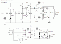
I want to build this acoustic guitar amp, I have 95% of the components and the chassis has been cut out and mostly drilled and powder-coated, the schematic...well...wondering if anyone would care to comment if they can see obvious bad things, or suggest improvements. The amp is for a niece, her acoustic guitar has a piezo pickup with an inbuilt 9V battery-powered preamp with volume and tone controls. The transformers are from Chinese hifi amps, just using up what I have. I chose the 6GK5 since I have some and I think only a single gain stage is required here. Could be wrong though. Open to any suggestions before construction commences. Thanks.
Edit: Of course, the design is not original, there are bits and pieces from contributors on this forum all tacked together somehow...
Edit: Of course, the design is not original, there are bits and pieces from contributors on this forum all tacked together somehow...
Attachments
Last edited:
Add a 1M resistor from the volume pot slider to ground. This means the valve still gets bias when the slider lifts off the track. Better still, add a coupling capacitor too so grid current does not make the pot noisy. The bias circuit should also ensure that bias still happens when sliders lift off tracks.
Why is there a 1M resistor feeding the phase splitter? Is this to add an HF roll-off?
With a stabilised screen supply you will also need a stabilised bias supply. Alternatively and more simply, you could have both unstabilised but then you would need to ensure that they are stable with signal - fat capacitors!
The 1M resistor feeding the phase splitter prevents undesirable effects when the cathodyne is overdriven, and lowers the grid voltage a little due to quiescent grid current. The Miller effect is not a problem due to the high input impedance, like in a cathode follower. Well that is how I interpret what I have read from Merlin Blencowe's book on guitar preamps. Maybe a 470K would do better in this position for this amp. Not sure if the neon will strike with a 1M either.
I was thinking unstabilized bias supply since if the mains voltage rises, the bias will become larger negative?
The screen supply is straight from Pete Millett's DCPP amp, it looks simple and the voltage can be adjustable if required.
Thanks for the German schem Wavebourn, it all helps.
I was thinking unstabilized bias supply since if the mains voltage rises, the bias will become larger negative?
The screen supply is straight from Pete Millett's DCPP amp, it looks simple and the voltage can be adjustable if required.
Thanks for the German schem Wavebourn, it all helps.
I think the 1M is there to protect the PS grid from excessive current if the previous stage cuts off. It will introduce a little distortion due to normal grid current, but this might not be noticeable in a guitar amp. An alternative is a smaller resistor (or none at all, as the 100K anode load in the previous stage has the same effect) with the neon replaced by a silicon diode, such a 1N4148.
The general rule with grid bias supplies is that the control grid and screen grid supplies should both be stabilised, or both unstabilised. This is because they have opposite effects so tend to cancel provided they roughly track each other. Stabilising just one of them can make anode current variation worse than having both unstabilised.
The general rule with grid bias supplies is that the control grid and screen grid supplies should both be stabilised, or both unstabilised. This is because they have opposite effects so tend to cancel provided they roughly track each other. Stabilising just one of them can make anode current variation worse than having both unstabilised.
I think the 1M is there to protect the PS grid from excessive current if the previous stage cuts off. It will introduce a little distortion due to normal grid current, but this might not be noticeable in a guitar amp. An alternative is a smaller resistor (or none at all, as the 100K anode load in the previous stage has the same effect) with the neon replaced by a silicon diode, such a 1N4148.
I have 470K/470K voltage divider in my Pyramid amps; both to protect grid from destructive current, and to allow higher anode voltage for the 1'st tube.
Neon lamps in such low current places are used as low voltage spark gaps.
The neon won't do anything, apart from protect the grid during warm-up. The forward grid current when hot will drop enough voltage across the resistor that the neon will never reach its firing voltage of 60-70V.
The general rule with grid bias supplies is that the control grid and screen grid supplies should both be stabilised, or both unstabilised. This is because they have opposite effects so tend to cancel provided they roughly track each other. Stabilising just one of them can make anode current variation worse than having both unstabilised.
Got it, I understand. Ok I will use zener or zeners on the bias supply as well. Won't be too hard to do that. I wanted the screen voltage regulator to keep the power down a bit with the high B+, I only need about 30W.
One other question I have is, should I have a capacitor somewhere as a low pass filter to prevent frequncies over 10 to 20KHz from reaching the OPT? Or is it that, since there is no negative global feedback, this is not required?
With no global NFB you won't have the stability problems which affect hi-fi amps. Whether you want to limit high frequencies is a matter of voicing, which is outside my experience. I guess an OPT intended for a guitar amp is quite likely to have a lower HF resonance frequency than a hi-fi OPT, so it may be best to keep signals away from it.
One other question I have is, should I have a capacitor somewhere as a low pass filter to prevent frequncies over 10 to 20KHz from reaching the OPT? Or is it that, since there is no negative global feedback, this is not required?
In terms of sound (not electronics), acoustic guitars provide plenty of nice sparkly harmonics in the high frequencies. Be careful not to filter them out. That of course also depends on the bandwidth of the piezo pickup, the speaker(s) being used, and the amount of finger grease that has accumulated on the strings, all of which may already be filtering those harmonics. In the studio, we'd always use new strings or boil the old ones for that reason (if they are steel, we wouldn't boil nylon strings).
At the other end, acoustic guitars have very little bottom-end below say 80Hz, so it wouldn't hurt anything to roll that off if needed.
..Todd
Last edited:
One other question I have is, should I have a capacitor somewhere as a low pass filter to prevent frequncies over 10 to 20KHz from reaching the OPT? Or is it that, since there is no negative global feedback, this is not required?
It's a question of 'suck it and see.' Electric guitar amps are usually built with transformers that would be considered inadequate for hi-fi. This gives a characteristic distortion and compression which is actually sought-after. This being an acoustic guitar, it will probably benefit from a cleaner sound but it's hard to be prescriptive. The best thing would be to try it in different configurations and get her to pick her preference. Awkward, but probably the best thing.
w
All great advice, thanks everyone. I will build it and fine tune if needed. The OPT came from a 6L6 Chinese hifi amp, I could never get that amp to sound right until I fitted a pair of Hashimoto's, so I am hoping this OPT will do OK for guitar.
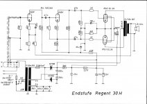
I bolted up all the bits just to get some visual progress, wiring up will happen this weekend. I simplified the schematic and dropped the regulated screens and regulated bias for now, I am thinking just go simple at first, since it's my first guitar amp, best to have a listen to the simple version first.
Attachments

All up and running, the 12AX7 phase splitter seems to break up in a not nice way, (farting) but substituting a 12AT7 is smooth all the way to 10. There is lots more distortion than I expected with a standard electric guitar plugged in, sounds quite good, much more distortion than an old Fender Twin but shy of a Marshall with master volume. There is a gain of around 50 in the 6GK5 alone. The clean sound before breaking up is very nice. The tone or freq response is quite well-balanced for an amp with no tone control. No smoke or hot bits so far. If the volume control is wound up to 10, the B+ drops from 440V to 400V, and the screen voltage from around 405 to 300V. The preamp would be getting around 360 to 320V. Hum levels are fairly low. Sounds like around 30 to 50W maybe. I was expecting it to be a lot cleaner, but I guess that's how you learn, build it and see what happens, then tweak tweak tweak.
I'm doing something wrong here...
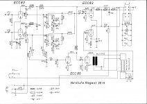
Hmmm, testing shows the amp is barely making 20W. Very puzzling. When the output starts to distort, with grid voltages approaching zero, I measure 2.6 to 2.7V peak across the cathode resistors, indicating a peak current draw around 173mA, which seems low. The anodes of the output tubes are at 200V RMS, which is also low. The grid voltage is -19V which gives approx 33mA quiescent cathode current (0.5V across the 15 ohm cathode resistors). I get about 10V RMS at the output into a 5.4 ohm load resistor. If anyone has any help to offer that would be good. Here's the current schematic. I guess I am wondering this, if the grids are being driven close to zero volts, why is the amp not making full power?
Hmmm, testing shows the amp is barely making 20W. Very puzzling. When the output starts to distort, with grid voltages approaching zero, I measure 2.6 to 2.7V peak across the cathode resistors, indicating a peak current draw around 173mA, which seems low. The anodes of the output tubes are at 200V RMS, which is also low. The grid voltage is -19V which gives approx 33mA quiescent cathode current (0.5V across the 15 ohm cathode resistors). I get about 10V RMS at the output into a 5.4 ohm load resistor. If anyone has any help to offer that would be good. Here's the current schematic. I guess I am wondering this, if the grids are being driven close to zero volts, why is the amp not making full power?
Change 5K4 (PS) with 1K/5W or choke (5-20H/50mA), connect 2x180 ohms(PS) parallel in positive side, connect negative side of bottom 82uF/350V direct to ground, change 15 ohms resistors (cathodes EL34) with 1 ohm/1W, etc...
Yes, I think davorin is giving good advice. Your HT supply has a bit too much resistance (unless you want droop), and the screen supply is a bit low. What does g2 drop to under load? You could just try changing the 5k4 to something smaller (1K?) and see if that is sufficient. You will need to rebias after doing this.
Schematic shows bias adj range of -32 to -51 but you mention -19. Are the 15ohmers accurate? -19 sounds too hot and would trigger clipping when the input approaches 19pk volts.
Thanks for the ideas. Will try your suggestions Davorin in a few days, I have to clear my workbench (dining room table) for a few days as we are having a party and lots of visitors. I was worried about the high B+ hence the two 180 ohm resistors in the PS. It is 490V unloaded.
I did some more measurements today. DF96 the screen voltage drops to 320V at clipping at the tube screen pins, it sits at 350V but drops to 320 at peak signal current.
jjman I checked the 15 ohm cathode resistors and they are 15R. Now the -19V, I must have got confused because I do not measure that today. I get -34.7 and -35.2 from the bias ccts, and -27.8 and -27.3 at the g1 grid pin at the tube.
It seems the cathodyne has no trouble driving the EL34 so far, and only gets flat on the peaks when output tube grid current starts to flow, which is when clipping begins (crossover distortion with flattened peaks and valleys). I tried a different set of outputs EH EL34, no difference. It just seems that the output power doesn't match the datasheet, by a fairly large margin. I wonder if its just the cheap output tranny. Either way, I will fit 1 ohm cathode resistors, raise the B+, and fit 1K vs 5K4 for the screens, rebias and see what happens. Won't happen for a few days though. Thanks for the help!
- Status
- Not open for further replies.
- Home
- Live Sound
- Instruments and Amps
- EL34 PP acoustic guitar amp