hi
Any one have experience, or schematics of amps with EL34´s running in serial ?
(warning, im just a guitar player, im not a tech wiz, so dont waste too much energy on this, just give some examples if any, thanks)
Any one have experience, or schematics of amps with EL34´s running in serial ?
(warning, im just a guitar player, im not a tech wiz, so dont waste too much energy on this, just give some examples if any, thanks)
Last edited:
Does he mean parallel, or cascade (i.e. using an EL34 as a voltage amp to drive an EL34 output). Assuming the latter, what would he hope to achieve?
Like the same-drives-same designs by Sakuma.
Hi - thanks- is that a reference - I tried google, cant find it - if so a, link would be of help.
I just found this video on youtube - it uses an (expensive) interstage transformer.
YouTube
Also someone did it with EL84.
Direct Coupled EL84-drive-EL84 Single Ended Amplifier | Foxtrot 9 Audio
Surely one can also AC couple them (use a coupling capacitor between anode of first tube and grid of second tube), keeping voltages lower than the above DC coupled unit.
Generally one would say using an EL34 as driver is a waste of resources (like the 1.6A heater, compare that to 0.3A for a 12A*7 tube) and increased complexity and costs (need for bigger transformer, high current around the sensitive driver stage) - but it can be done.
I think we may ask what you are trying to achieve with this?
Cheers, Erik
hi
Any one have experience, or schematics of amps with EL34´s running in serial ?
No. I have always used 12au7 phase splitter to drive EL34's.
As we tried to explain in your 6V6 thread it is true that using something bigger than a 12AX7 to drive an EL34 can produce some more power and sonic benefits by being able to drive the grid slightly positive.
Attempting to go beyond this point will blow stuff up. A 6V6 is overkill, an EL34 turned down to even a watt or two will blow the grid right out of another EL34. In reality the second tube will arc over internally and die, possibly taking out other parts like an output transformer. I have proven this by blowing up some 6L6 types by overdriving them.
For the technical readers:
Most of the typical audio output tubes can be saturated harder by pushing the grid positive. This is known as A2 in a SE amp, and AB2 in a push pull amp.
These modes are often documented in the data sheets for some tubes like the 6L6 family, and even the old 45 tube. There are no published AB2 typical operation specs or positive grid curves for the EL34 that I am aware of.
The typical RC coupled 12AX7 circuit found in most guitar amps can NOT do this and what is often called output stage clipping is actually the driver's inability to fully saturate the output tube. A typical audio output tube may still have 50 to 100 volts on its plate when the grid is at zero volts. This can be reduced by driving the grid positive, allowing for more power output and a sharper more harmonically rich saturation point.
Some tubes benefit greatly from AB2 operation. The lowly 50C5 tube found in old radios can crank out 20 watts per pair by ignoring all specs and driving the grids way positive. It does not blow up and will sit there for hours at this power level. Attempting to make 30 watts will however blow the SCREEN grid!
A pair of 6V6's can make 35 watts, 6AQ5's can make 25 watts. I did not test these to destruction.
The 6L6 family is specified for AB2 operation. The tube manual shows 55 watts from a pair on 450 volts in AB1 (no positive grid operation) but shows 47 watts will be obtained from only 360 volts in AB2. Even the conservative data sheet shows some extra power available by driving the grid positive. Since I have a big box full of crusty looking old 6L6GA's (not 6L6GC's) pulled from military scrap power supplies, I decided to find out what they would really do......
I had wired up a pair of these tubes with lab power supplies and a driver board capable of stuffing the grids with all they could eat and proceeded to extract big power from some 75 year old tubes. There were 1 ohm 1% 2 watt resistors in series with the cathodes for current monitoring. I had two pair cranking out 100 WPC in a HiFi stereo amp for 15 minutes or so with no ill effects, nothing inside the tubes were glowing except the cathode, so I turned up the drive to reach 110 watts out and after a few seconds, BANG. One of the cathode resistors exploded. I replaced the resistor and cranked it up again. The tube had survived, and proceeded to make 100 WPC again. A second attempt to push beyond 100 watts resulted in a different cathode resistor exploding. The tubes however survived.
TV sweep tubes generally have sufficient cathode emission such that they can be saturated down to the 10's of volts region at zero grid volts. AB2 operation is not needed. Was there any benefit to doing it anyway? Well, I have two EXPLODED TUBES to say that there isn't much benefit, and plenty of risk. One of the tubes shattered violently scattering glass all over the room. The other just cracked around the base from serious plate current.
Autopsy on one of the dead tubes revealed that a tube arc from cathode to plate occurred. Minimal damage to the internals occurred, but the large current pulse caused the leads to blow where they passed through the glass base shattering the tube. This current pulse caused the core of the OPT to become strongly magnetized resulting in high distortion.
The 6L6GA's likely had a similar arc, but the blown cathode resistors saved the tube.
Attempting to push tubes where they were never intended to go can (and often will) result in dead parts, and should not be attempted by those who don't fully understand the risks. Even then one needs to decide where to draw the line. An acceptable level of unreliability is allowed for an experimenter in his work space. That level is far lower for a musician on stage in front of an audience.
Either way, an EL34 or even a 6V6 is not needed to find the drive limits of a pair of EL34s. The EL34 is not an easy tube to make. It requires alligned grids to keep the screen current down and many current production EL34's are at the edge of meltdown already due to poor alignment. I have not hammered on any of them for this reason.
Power amplifierHi - thanks- is that a reference - I tried google, cant find it - if so a, link would be of help.
wow - that looks like some really expensive stuff. Very interesting.
As we tried to explain in your 6V6 thread it is true that using something bigger than a 12AX7 to drive an EL34 can produce some more power and sonic benefits by being able to drive the grid slightly positive. <snip>
This is exactly the kinda of stuff I wanna read.
Well in this Tread, I had a slightly different objective.
So going from the plate of nr1. EL34 - to the grid of the nr.2 El34 What do i need to put in between them: Would it be possible just with - a resistor and a capacitor Or would I have to go through a transformer and a 3rd party attenuator - or another combination
An EL34 is serious overkill for driving an EL34, so the advice is don't do it. If you want to drive an EL34 into grid current then first you need to find some data, then you can decide how much power you need in the driver, then you can choose a suitable driver, then you can start thinking about design. A transformer or cathode follower will be needed.
The fact that people have in general not done this with EL34 may be something to think about.
The fact that people have in general not done this with EL34 may be something to think about.
Thanks - well its not because I want to drive it in the traditional way - Í had another Thread here about using a 6V6 for exactly that - and it got a bit hairy.
This is more about, if there is a way its possible to stack the EL34´s, without killing your amps. Putting them in series, because I love the sound.
This is more about, if there is a way its possible to stack the EL34´s, without killing your amps. Putting them in series, because I love the sound.
Last edited:
Thanks - well its not because I want to drive it in the traditional way - Í had another Thread here about using a 6V6 for exactly that - and it got a bit hairy.
This is more about, if there is a way its possible to stack the EL34´s, without killing your amps. Putting them in series, because I love the sound.
Sorry for being negative again, you love the sound of putting them in series? Of overdriving an EL34? Which amp do you like the sound of and were do you play it, does it have to be reliable (ie. on the road).
Using standard capacitor coupling will get you very little driving one tube into the other over a 12AT7 or the like. The grid of a tube is relatively high impedance with a negative voltage on it as compared to the cathode. You need to drive it positive compared to the cathode. You need a transformer or going SS a Mosfet with the associated power supplies.
This is not newbie stuff. Build a simple amp first, a Tweed 6G2 Princeton. Find out what the stages do and how they operate. You want to do surgery and you haven't held a scalpel yet from what I perceive. Do you have a DMM? Scope? Signal generator? Sorry, ears won't do where you want to go. So you slam the tube, how are the output transformer and power supply going to take it? There is more to building a hotrod then stuffing a big motor in a car.
And the big thing, will the sound be any better than a current amplifier? You get more power but I get the feeling you want to hear the overload characteristics. The higher up the Class AB2 curve you go you delay the clipping. George may be able to answer the question. How much farther (more signal voltage) do you need to take the tube as far as it can go?
Say the 6V6?
An externally hosted image should be here but it was not working when we last tested it.
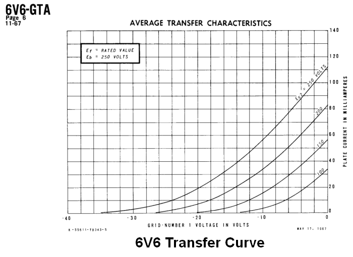
With the above curves say we need 35V P-P to get a fully clean output. (single tube, not in P-P) Will we need 50V P-P to drive it into AB2 until we start getting clipping? So this means your drive circuit must put out a greater voltage. And if you want more than clean output you need a much greater signal voltage. Or you have your preceding stage clip at this point.
So I comend you for chasing an idea (I have done my own). But this is not a case of just slapping something together. Well, that is unless George does it. 😉
Looks like you want to "do things in an unconventional way" but with no clue.Thanks - well its not because I want to drive it in the traditional way - Í had another Thread here about using a 6V6 for exactly that - and it got a bit hairy.
I suggest you try square wheel cars, quite unconventional too.
NoThis is more about, if there is a way its possible to stack the EL34´s, without killing your amps.
Putting them in series, because I love the sound.
How would you know? 😕
You have NEVER heard that combination so it´s just your imagination.
plate from 1st el34 in to grid of 2nd el34........Like the same-drives-same designs by Sakuma.
Some of Sakuma's designs did use one tube to drive another identical tube. This was done for exactly the opposite of what you are trying to achieve. All tubes distort the signal to some degree. Each stage in a typical common cathode design operates out of phase with the stage before it, so it was assumed that the identical distortions created in identical but out of phase tubes would cancel each other resulting in less overall distortion. This does work to some degree in practice, but total cancellation would require identical signal levels in perfectly matched tubes.
I just found this video on youtube - it uses an (expensive) interstage transformer.
This is a Sakuma design intended for distortion cancellation.
Direct Coupled EL84-drive-EL84 Single Ended Amplifier | Foxtrot 9 Audio
Same premise, just without the transformer.
Would it be possible just with - a resistor and a capacitor Or would I have to go through a transformer.........Surely one can also AC couple them (use a coupling capacitor between anode of first tube and grid of second tube
You could string 2, 3 or more identical tubes in "serial" including EL34's and make a working amplifier. Connecting them together with the typical resistors and capacitor would also work, and possibly sound good for the same purpose as these designs, a HiFi amp operated well below clipping.
As I explained in your other thread you could use the biggest "power tube" on the planet as a driver and you will only create huge blocking distortion if you use a resistor and capacitor to couple them. The result wouldn't be much different than a 12AX7 driver untill you really cranked it, at which point the EL34 would distort in a ugly manner until blocking shut it off completely.
A properly made driver transformer designed specifically for driving "power tubes" was the hot ticket in the 40's and 50's when tubes were more expensive than small transformers. We have better ways today. As I explained before one would use a vacuum tube cathode follower circuit or a mosfet follower circuit today. If you want to use a transformer, they are still being made. I have used them in such designs years ago:
Universal Interstage Transformer UIS-1 MADE IN USA
Today I would use a mosfet follower since they can drive the "power tube" much harder than a transformer. As I stated in the 6V6 thread, the key here is knowing the tube's limits because you can drive tubes hard enough to blow them up. I explain the theory here:
Power Drive | Tubelab
George may be able to answer the question. How much farther (more signal voltage) do you need to take the tube as far as it can go?
On a tube like the 6L6GC where positive grid curves are given it's possible to predict the grid voltage needed to fully saturate the tube. You would need to know the necessary peak current required in the output tube.
This is usually done by assuming the speaker is 8 ohms, and B+, the ratio in the OPT is known, so the peak current is simply the load impedance on a single tube is the plate voltage divided by 1/4 the OPT impedance. A guitar speaker with the cone in motion can be anywhere from 2 ohms to 30 ohms, so real predictions are impossible.
Even if we knew the peak current, positive grid voltage curves don't exist for the EL34, and EL34's are easy to blow up, so I haven't explored that area of their operation. Just by looking at the curves, the saturaton "knee" is rather rounded and the peak current at zero grid volts is pretty high, so I would GUESS that it wouldn't take a whole lot of drive voltage to fully saturate one.
As with ANY endeavor to take a tube where it has never been before, experimentation by someone with good experience in vacuum tube design would be needed, and the likelyhood of blowing some stuff up before achieving what you are looking for is pretty high.
If you or a knowledgeable tech were to venture down this path, I would try the transformer approach first since it is the easiest, and least likely to blow stuff up.
Start with something smaller and cheaper than EL34's for drivers too. Even the 6V6 makes more sense. The cheaper 6AQ5 is essentially a miniaturized 6V6 and sounds very similar. A pair will make 10 watts by the book, and 20+ when pushed, so they are still overkill, but more sane that a pair of EL34's to drive more EL34's.
- Status
- Not open for further replies.
- Home
- Live Sound
- Instruments and Amps
- EL34 in serial