Hi,
I just bought and received a EL34 based DIY amp, knowing there is a clearly noticable hum produced by the device, but I consider the amp as my learning by doing project( and it was around 80€). The amp uses 2x Mullard EL34 xf4 as power tubes, and a ECC83 as pre (Sovtek). I also received an additional 2x Telefunken ECC83 and Tungsram ECC83. I currently have the Sovtek ECC83 plugged in.
I think the first start to get to proper help is drawing the circuitry. What tools/software would you recommend?
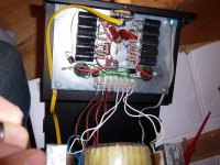
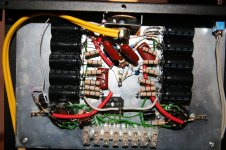
Maybe it is a common circuitry and someone recognizes it instantly, so I will attach some pictures of it.
Any immediate ideas on the humming origin?
I just bought and received a EL34 based DIY amp, knowing there is a clearly noticable hum produced by the device, but I consider the amp as my learning by doing project( and it was around 80€). The amp uses 2x Mullard EL34 xf4 as power tubes, and a ECC83 as pre (Sovtek). I also received an additional 2x Telefunken ECC83 and Tungsram ECC83. I currently have the Sovtek ECC83 plugged in.
I think the first start to get to proper help is drawing the circuitry. What tools/software would you recommend?
Maybe it is a common circuitry and someone recognizes it instantly, so I will attach some pictures of it.
Any immediate ideas on the humming origin?
Attachments
I think the first start to get to proper help is drawing the circuitry. What tools/software would you recommend?
LT Spice can be used for this purpose as well and is free.
Looks a bit like a junk box - just worth the tubes. Considering Epay prices, 80€ is not bad.
Pin-3 and Pin-4 on the EL34 are connected which means triode connection. This makes sense because there are only two wires going to the output transformer, which means no feedback.
The schematic is certainly some standard & simple triode-triode-cap-coupled arragement.
The wiring and build quality is horrifying:
Power resistors directly soldered to electrolytic caps is a no go because of thermal conductivity.
insulating screw joints inside an amplifier and using soldered in them is bad and often results in loose contacts. (Solder tends to kind of flow away under pressure like a cooled down amorphous liquid)
All-over-the-place AC heater wiring (Hum !)
Huge loop from AC rectifier to the filter caps. (Hum !)
Big Toroid derictly besides the OPTs - might induce hum.
What's the size and specs of the OPTs ?
The only creative thing as far as I can see is the signal lamp/LED. It seems to be integrated in the volume knob and is turned with it 😎
The wiring and build quality is horrifying:
Power resistors directly soldered to electrolytic caps is a no go because of thermal conductivity.
insulating screw joints inside an amplifier and using soldered in them is bad and often results in loose contacts. (Solder tends to kind of flow away under pressure like a cooled down amorphous liquid)
All-over-the-place AC heater wiring (Hum !)
Huge loop from AC rectifier to the filter caps. (Hum !)
Big Toroid derictly besides the OPTs - might induce hum.
What's the size and specs of the OPTs ?
🙄
Don't get me wrong, that thing does sound quite nice besides the hum, and is more powerful than 2x7W in comparison.
The heater wiring is which color? Red?
I also found KiCAD as means to draw the circuit, which one would you recommend?
The OPT have no specs on them, they are sized (metal frame) 6x5x3cm.
A TDA2030 does, too ! 😛 Since I never listened to music playing from that amplifier, I won't discuss anything about that subjective thing called "sound". I just commented on the pics.🙄
Don't get me wrong, that thing does sound quite nice besides the hum,
Doubt that. Lets look in that fancy TFK datasheet:....and is more powerful than 2x7W in comparison.
An externally hosted image should be here but it was not working when we last tested it.
(Assuming you run the according voltages and currents)
At 6W we already have a whopping 8% of distortion. If you squeeze out more then 7W from a trioded EL34 you just prove that you like extreme amounts of even harmonic distortion 😀
Furthermore, a single ECC83 may not be most suitable tube for a ~19V RMS.
The heater wiring is which color? Red?
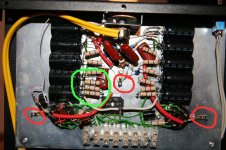
The green wires. the screw joints on the left side with the big wires from the toroid.
I mostly use a pencil, a rubber and a sheet of paper. I use Altium for schematics, but it's expensive. A long time ago I used EAGLE which is free. Another way is LTSpice. But, again, a scanned paper sheet with a pencil drawing is fine.I also found KiCAD as means to draw the circuit, which one would you recommend?
Simply draw the circuit with a pencil and paper.
Separate the power supply and the audio circuit.
The audio circuit is just a pot going to the driver tube, cap coupled to the EL34 grid to a output transformer. To see if it has feedback, look for a wire from the output secondary (speaker out) back to the input tube.
The power supply is just a transformer to a Full Wave Bridge rectifier to caps, then resistors then caps. CRCRCRC filter.
There is no horrible fundamental problem with the amp other than layout. It will make a clean 5 watts in triode.
🙂 Yep, let us just say: I heard much worse! If you wanne take a listen come to Nürnberg 😀A TDA2030 does, too ! Since I never listened to music playing from that amplifier, I won't discuss anything about that subjective thing called "sound". I just commented on the pics.
😀If you squeeze out more then 7W from a trioded EL34 you just prove that you like extreme amounts of even harmonic distortion
Speaker sensitivity could have tricked me there!It will make a clean 5 watts in triode.
These I could reroute quite easily, enough room!The green wires. the screw joints on the left side with the big wires from the toroid.
Comes from the CRCRCRC filter , goes back to the tubes. If heater pins are 2 and 7, it goes back to 3 and 4.To see if it has feedback, look for a wire from the output secondary (speaker out) back to the input tube.
Whoo, that will take me some time. I have resorted to the pencil/paper method for now, that suits the novice much better, I have to redraw a lot... I have finished 40-50% (the "left side" and parts of the ECC83)
What I noticed is that from the rectifier (KBU 6M) pin4 feeds the filter array, pin1 only goes to the "left side" EL34 (pin1&8). Why is that, I would have expected symmetrical layout?
... using LTSpice for drawing the traced-out circuit has an additional advantage, besides a decent schematic editor: You can simulate the circuit 🙂
Greetings,
Andreas
Greetings,
Andreas
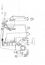
I attached my first ever circuit drawing with no corrections made. This must be funny to see for pros. 😱 (Just the "left" side/channel)
And some questions:
1) Can I simply deactivate the volume knob LED by cutting the elements at the spots marked with crosses?
2) The places with red circles around them: Are those ground points, or is the mounting plate made from aluminum and are those just soldering points?
3) Can someone explain why the constructor used three resistors in a row instead of one at the place with the green circle?
Attachments
nightyy;3355870 And some questions: 1) Can I simply deactivate the volume knob LED by cutting the elements at the spots marked with crosses? 2) The places with red circles around them: Are those ground points said:1) Yes, you can. remove the LED/wiring from the knob too, to avoid it becoming entangled somewhere it shouldn't.
2) They seem to be used as ground points with the chassis as common ground plane. Not a good practice, better use isolated posts there and employ a correct grounding scheme.
3) Two reasons possible: a) Three (equal) resistors have a higher voltage capability than one, because the voltage drop is now 1/3 over each resistor body. b) Same for dissipation rating. Each of the three (equal) resistors has to dissipate 1/3 of the power a single one would have to.
Rundmaus
Well I don't want to hurt anyone's feelings, but I think I'd tear that down to the basics and totally rebuild it.
Thanks!1) Yes, you can. remove the LED/wiring from the knob too, to avoid it becoming entangled somewhere it shouldn't.
2) They seem to be used as ground points with the chassis as common ground plane. Not a good practice, better use isolated posts there and employ a correct grounding scheme.
3) Two reasons possible: a) Three (equal) resistors have a higher voltage capability than one, because the voltage drop is now 1/3 over each resistor body. b) Same for dissipation rating. Each of the three (equal) resistors has to dissipate 1/3 of the power a single one would have to.
No way to hurt anyone, except the builder is around here 😀 Anyone feeling guilty?Well I don't want to hurt anyone's feelings, but I think I'd tear that down to the basics and totally rebuild it.
I just want to achieve a understanding of the circuit and be able to do schematics, then take a look where the hum comes from, which probably means some rewiring. I honestly don't know why the builder laid it out so crammed. There is still 4-5 cm on either side of the CRCRCRC array.
Or would you argue to use another circuitry altogether?
N4BBQ's suggestion sounds very good - at least it would mean getting the most learning out of it.
I would suggest the following:
a) trace out the schematic and redraw it nicely
b) ask for opinions and modifications here
c) rebuild it avoiding all those mistakes that have already been pointed out
This will provide a lot of understanding, I expect.
Greetings, and have fun!
Rundmaus
I would suggest the following:
a) trace out the schematic and redraw it nicely
b) ask for opinions and modifications here
c) rebuild it avoiding all those mistakes that have already been pointed out
This will provide a lot of understanding, I expect.
Greetings, and have fun!
Rundmaus
Thanks for your advice,
I have redrawn the schematics a second time, looks much better already, I'll redraw a third time and post that, maybe you could all help pointing out flaws.
General question on cabling:
You pointed out the heater wires could induce hum, I guess caused by magnetic fields. Coming from IT I would rewire those heating connections with drilled and shielded CAT7 cable (solid copper core). The drill and the EM shielding should both help against magnetic inductions?
I have around 100m CAT7 twin cable around, and I can extract 4x 2 shielded pairs from each cable. But I have never seen the use of shielded wiring in my amps or other DIY amps? Bad idea?
Well your drawing shows one tube with the cathode (pin 8) and supressor grid (pin 1) tied together, then to ground through a cap/resistor parallel circuit, and the other tube shows them separate.
And on the control grid (pin 5); one tube has the input coming in, with the grid terminated with some R to ground, and the other tube show the grid tied directly to ground.
You may want to check those again.
And on the control grid (pin 5); one tube has the input coming in, with the grid terminated with some R to ground, and the other tube show the grid tied directly to ground.
You may want to check those again.
Last edited:
- Status
- Not open for further replies.
- Home
- Amplifiers
- Tubes / Valves
- EL34+Ecc83 amp hum