Originally posted by theduke
I feel like connecting the amplifier circuit ground to the pre-amplifier ground but not to that Schutzleiter ("house ground").
Yes you can do it that way. Verify that the preamp chassis is at mains/earth ground. And your preamp outputs, whether the signal ground is connected directly to the mains/earth, chassis ground (1) or through a resistor/cap network -> to earth/chassis ground (2).
If leaving both grounded at the outlet and you have no or the least hum or no ground loop, leave it that way!
The RCA input jacks of the amp are connected directly to the chassis, your interconnects will carry the ground fault condition also.
So if (1) and you run a ground wire from the amp chassis to the preamp chassis you may create a ground loop. If the ground returns of the preamp outputs are directly connected to -> chassis -> mains/earth ground and you lift the safety/earth ground of either the amp or preamp, the connection will be made through the interconnects. That would make some a little uncomfortable!
But here's a better way to deal with condition (1),
Simular to condition (2) but here we'll create it in the amp:
1. Buy two insulated RCA jacks and install them in the amp.
2. Connect/Solder a 100R-470R resistor and a 10nF-22nF 500V or higher (1kV) ceramic disc capacitor from where the PSU and signal (driver pcb) grounds meet on the PSU pcb to the solder pad/screw where the mains safety ground connects.
You can also install these components near the input jacks if you have the necesary hardware. This may or may not be the best location though.
3. Ground both at the outlet.
4. All Done!
So if (2) leave both grounded at the outlet.
Make D8mn sure the fuse is wired into the HOT side of the mains!
 Which here in the US is the black wire, which measures 120V with respect to earth ground (green wire). The white neutral wire should measure a few millivolts with respect to earth ground. The reason for that is that all wire has a resistance. So the more devices you have running, drawing current, the more voltage drop you'll have. If it's a few tens of volts you've got a big problem! (Actually neutral isn't really neutral. It's the return for the black, live wire.) The white neutral wire is supposed to be connected to earth ground at the distribution-breaker-fuse box, but don't count on it! The neutral wire is also supposed to be connected to earth at the step-down transformer on the pole, but don't count on that either! Actually in some homes the wiring is wrong, so best to measure!
Wayne zzzaapppp!
thanks wayne,
if you do have a complete schematic including the output tubes i would love to try it.
jojod
if you do have a complete schematic including the output tubes i would love to try it.
jojod
thanks wayne,
if you do have a complete schematic including the output tubes i would love to try it.
jojod
Your welcome! I'll work on it today for you and geeit it posted asap. Are you really set on an ECC83-82? I can think of better possibilities. All 9 pin or octal? There's all kinds of PP EL34's all over this forum! I'll give it a shot tho. 😀 I'm bored anyway, I guess I need something to do!

Wayne
BTW you think maybe best to start a new thread? I think so since this one is getting a little jumbled 😉
@cogsncogs
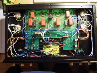
I have made a picture of the inside, have a look. You can see that i already used a blank screw to fix the psu middle to the chassis. I scraped the paint away from the chassis at this point. Maybe looks a little messy. The red caps are WIMA MKP's, which are used quite often in audio circuits I believe. The black Visaton is the 1uF MKP from the input stage (screen bypass of 6F2 not coupling cap!). I used it because of it's 20mm mounting distance but it's designed for crossovers so I guess it will be ok. Of course I changed the output terminals and got me some real RCA inputs along with. These Terminals are hell to solder, I found out (I want to connect the wire to the inner rod and not to that flimsy thing besides).
Ah, and if you winder how i mounted the amplifier board, that's etched flipped-over! So my copper side faces upwards, but as you can see it's better for me anyway! I wonder why it is designed to be on the other side in the first place...
How have you done the feedback resistors? Switching them😕
whoo, done that😉Make D8mn sure the fuse is wired into the HOT side of the mains!
I have made a picture of the inside, have a look. You can see that i already used a blank screw to fix the psu middle to the chassis. I scraped the paint away from the chassis at this point. Maybe looks a little messy. The red caps are WIMA MKP's, which are used quite often in audio circuits I believe. The black Visaton is the 1uF MKP from the input stage (screen bypass of 6F2 not coupling cap!). I used it because of it's 20mm mounting distance but it's designed for crossovers so I guess it will be ok. Of course I changed the output terminals and got me some real RCA inputs along with. These Terminals are hell to solder, I found out (I want to connect the wire to the inner rod and not to that flimsy thing besides).
Ah, and if you winder how i mounted the amplifier board, that's etched flipped-over! So my copper side faces upwards, but as you can see it's better for me anyway! I wonder why it is designed to be on the other side in the first place...
How have you done the feedback resistors? Switching them😕
Attachments
OOOPPPS!  🙁
🙁 
I hate to tell you this butt...your TOOB sockets for the 6F2 will now be mounted backwards, unless you want your tubes mounted inside the amp chassis! Pin 1 will no longer be connected to the foil trace for PIN 1 But PIN 9!!!
I wanted to do it that way also but as you can see if you think about it for a minute...
Sorry
Wayne
🙁 So my copper side faces upwards, but as you can see it's better for me anyway! I wonder why it is designed to be on the other side in the first place...
I hate to tell you this butt...your TOOB sockets for the 6F2 will now be mounted backwards, unless you want your tubes mounted inside the amp chassis! Pin 1 will no longer be connected to the foil trace for PIN 1 But PIN 9!!!
I wanted to do it that way also but as you can see if you think about it for a minute...
Sorry
Wayne
uumm, no. I mounted the tube sockets at the foil side. This is possible because the pins are standing outwards a bit. I'll check it once again but I think I got the pins right.
You know I did not just flip the board, it is really printed mirrored left-right! A pruduction fault.
theduke
You know I did not just flip the board, it is really printed mirrored left-right! A pruduction fault.
theduke
You know I did not just flip the board, it is really printed mirrored left-right! A pruduction fault.
Well if that's the case then MY pcb is the production fault or yours is a revised version! Dang! Hey, wanna swap boards 😀
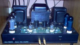
Here's a pic of mine looking from the topside/front:
I hope you're right!
Wayne
Attachments
After looking more closely at your PCB where the tube socket mounts, everthing looks spot on!
9AE starting at top right pin as seen in picture, going clockwise:
1 - triode anode
2 - pentode grid
3 - pentode screen grid
4 - filament
5 - filament
6 - pentode anode
7 - pentode cathode, suppressor grid G3
8 - triode cathode
9 - triode grid
Looks great! 😎
Wayne
9AE starting at top right pin as seen in picture, going clockwise:
1 - triode anode
2 - pentode grid
3 - pentode screen grid
4 - filament
5 - filament
6 - pentode anode
7 - pentode cathode, suppressor grid G3
8 - triode cathode
9 - triode grid
Looks great! 😎
Wayne
Wayne,
I already have the ECC82 and ECC83 tubes and would love to use them. Nothing special, just reliable and very good sounding please. 🙂
JojoD
I already have the ECC82 and ECC83 tubes and would love to use them. Nothing special, just reliable and very good sounding please. 🙂
JojoD
aht,
nice diy amp, unfortunately the resolution of the schematic you posted and the one you emailed me is the same. i can't read the values of the parts.
😀
nice diy amp, unfortunately the resolution of the schematic you posted and the one you emailed me is the same. i can't read the values of the parts.
😀
Re: Schematic again
if you do have a link i can follow then i'll be on my way. 🙂
thanks
aht said:Ummmm
Very easy to download at Antique soundlab website (not pcb)
if you do have a link i can follow then i'll be on my way. 🙂
thanks
@ aht
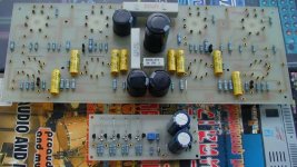
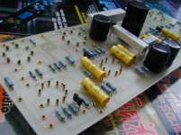
What exactly are you using for tube sockets? I'd like to try that someway-day! What's that small board with those eeh hemm transistors (FET's I hope)? Yeah I've made quit a few pcb's in my day... got about 5 gallons of ferric chloride and a nice stash of blank boards that's been calling my name!
Alright then, we can do that and if you decide to upgrade a little to better tubes at a later time it's very easy to do. Just have to change a few resistor values! 😎
Designing to the power supply will the trickiest depending on your ability to obtain the appropriate iron. A couple of questions; Cathode (self) bias or fixed bias? Self bias is easier and cheaper, but less power. Fixed bias; more complicated, somewhat more expensive and more power. Ultralinear or triode mode?
Are you dead set on using tube rectification? Tube rectification is more expensive (power transformer, choke, IRON!), soft start, less power from same transformer and less reliable. And some people find that tube rectification is a little shy in the bass department. Sand rectification much cheaper, more power and better reliability. And let us not forget rectifier switching noise, but with a good design and proper implementation it shouldn't be much of an issue. I'd opt for sand. Yeah I know a 5U4 is much nicer to look at and some people like the sound. We'll see. As for tube rectifiers of the 5U4 type I like the 5V3A/5AU4. But it's only available as NOS. 🙄
Wayne 🙂
What exactly are you using for tube sockets? I'd like to try that someway-day! What's that small board with those eeh hemm transistors (FET's I hope)? Yeah I've made quit a few pcb's in my day... got about 5 gallons of ferric chloride and a nice stash of blank boards that's been calling my name!
Originally posted by JojoD818:
I already have the ECC82 and ECC83 tubes and would love to use them. Nothing special, just reliable and very good sounding please.
Alright then, we can do that and if you decide to upgrade a little to better tubes at a later time it's very easy to do. Just have to change a few resistor values! 😎
Designing to the power supply will the trickiest depending on your ability to obtain the appropriate iron. A couple of questions; Cathode (self) bias or fixed bias? Self bias is easier and cheaper, but less power. Fixed bias; more complicated, somewhat more expensive and more power. Ultralinear or triode mode?
Are you dead set on using tube rectification? Tube rectification is more expensive (power transformer, choke, IRON!), soft start, less power from same transformer and less reliable. And some people find that tube rectification is a little shy in the bass department. Sand rectification much cheaper, more power and better reliability. And let us not forget rectifier switching noise, but with a good design and proper implementation it shouldn't be much of an issue. I'd opt for sand. Yeah I know a 5U4 is much nicer to look at and some people like the sound. We'll see. As for tube rectifiers of the 5U4 type I like the 5V3A/5AU4. But it's only available as NOS. 🙄
Wayne 🙂
Attachments

What's that small board with those eeh hemm transistors (FET's I hope)?
Looks like a circuit for the bias, but what are the transistors for. Ahhh, I think I know now, current sources?
Wayne
cogsncogs said:@ aht
What exactly are you using for tube sockets? I'd like to try that someway-day! What's that small board with those eeh hemm transistors (FET's I hope)? Yeah I've made quit a few pcb's in my day... got about 5 gallons of ferric chloride and a nice stash of blank boards that's been calling my name!
Alright then, we can do that and if you decide to upgrade a little to better tubes at a later time it's very easy to do. Just have to change a few resistor values! 😎
Designing to the power supply will the trickiest depending on your ability to obtain the appropriate iron. A couple of questions; Cathode (self) bias or fixed bias? Self bias is easier and cheaper, but less power. Fixed bias; more complicated, somewhat more expensive and more power. Ultralinear or triode mode?
Are you dead set on using tube rectification? Tube rectification is more expensive (power transformer, choke, IRON!), soft start, less power from same transformer and less reliable. And some people find that tube rectification is a little shy in the bass department. Sand rectification much cheaper, more power and better reliability. And let us not forget rectifier switching noise, but with a good design and proper implementation it shouldn't be much of an issue. I'd opt for sand. Yeah I know a 5U4 is much nicer to look at and some people like the sound. We'll see. As for tube rectifiers of the 5U4 type I like the 5V3A/5AU4. But it's only available as NOS. 🙄
Wayne 🙂
I have listened to a lot of fixed bias amps in ultralinear and i loved it. 🙂 But it doesn't need to be an ultralinear since it would be a learning amp as long as it's push pull. I would have built an ST70 clone since it uses tube rectifier but the 7199 is not reliably available locally. Besides, I already have a couple of fresh 5U4G rectifiers 😀 .
Wayne, thanks for the help.
JojoD
New amp finished
Yesterday, i switched on my new tube amp. And nothing blew up or burnt down! But I was doing some insane stuff like connecting the input to the pc soundcard and using my good self made speakers. To any newbie here: do NOT use your fine speakers for testing/adjusting of new equipment! It's scaring.
Anyway, everythings ok so far. With shorted out inputs nearly nothing can be heard out of the speakers. Tubes are glowing nicely from inside that thing (let me call it tube) in the middle.
Problems so far:
° I am not able to measure cathode voltage. It's 0.0V. Neg. bias is -63V at every EL34. I tried to adjust neg. bias. From somewhere near -50V the speakers start to rattle like crazy.
° After switching off, there is a loud "whoosh" with a 100Hz or 50Hz tone in it of maybe 2 seconds in the speakers and the big caps seem to have discharged quickly.
° When switching lights in the house a loud crack is in the speakers. The cabling of the rooms is a bit old and odd. Maybe I will use a mains filter or something.
Thanks in advance for any comments,
theduke
@ theduke
Sounds like you've got a problem!
Sounds like positive feedback. Remove one pair of EL34's. On the side that still has the EL34's; disconnect one side of the feedback (NFB) resistor. If the oscillation stops reverse the output transformer primary leads.
That's because at -63V grid bias the EL34 is at cutoff. When you decrease the neg bias voltage (-50V) the EL34 begins to turn on.
Sounds like motorboating!
If disconnecting the NFB resistor does not stop the oscillation, look to the power supply capacitors. A PSU cap that is not connected properly, ie left floating on one side will cause motorboating. Go over every connection starting at the power supply to make sure everthing is connected to where it's supposed to go. After checking all the connections and wiring, grab your DVM and start taking measurements with the output tubes removed. Then we'll be able to go from there.
BTW computer sound cards are nortorious for having DC on their outputs! %**#!^& junk, cheap &@$#@^*$!
Wayne
Sounds like you've got a problem!
After switching off, there is a loud "whoosh" with a 100Hz or 50Hz tone in it of maybe 2 seconds in the speakers and the big caps seem to have discharged quickly.
Sounds like positive feedback. Remove one pair of EL34's. On the side that still has the EL34's; disconnect one side of the feedback (NFB) resistor. If the oscillation stops reverse the output transformer primary leads.
I am not able to measure cathode voltage. It's 0.0V. Neg. bias is -63V at every EL34. I tried to adjust neg. bias. From somewhere near -50V the speakers start to rattle like crazy.
That's because at -63V grid bias the EL34 is at cutoff. When you decrease the neg bias voltage (-50V) the EL34 begins to turn on.
Sounds like motorboating!
If disconnecting the NFB resistor does not stop the oscillation, look to the power supply capacitors. A PSU cap that is not connected properly, ie left floating on one side will cause motorboating. Go over every connection starting at the power supply to make sure everthing is connected to where it's supposed to go. After checking all the connections and wiring, grab your DVM and start taking measurements with the output tubes removed. Then we'll be able to go from there.
BTW computer sound cards are nortorious for having DC on their outputs! %**#!^& junk, cheap &@$#@^*$!
Wayne
- Status
- Not open for further replies.
- Home
- Amplifiers
- Tubes / Valves
- EL 34 30W ultra linear