Hello all, I notice a lot of vintage tube intergrated amplifiers did not come with preamp out puts and my Eico St70 is one. I'm putting together a triamp system for a set 3way of speakers im building. My idea is using the Eico's phono and preamp section to drive all of it,use it's amplifier section to drive the midrange drivers and solid state amps on the low and hi frequency drivers. My problem is I need pre outs for the solid state amps. I'm not an engineer nor a designer but I can sure read and understand schematics. I've attached a couple pics of the Sam's Eico schematics for reference. Here are my thoughts. Could I come off V2b (7247) section behind the .1 capacitor before the low filter switch or go before the .1 cap add another .1 cap in series with the new pre out jacks, will I need a 47k resistor to ground at the pre out as well? Or will I need another gain stage? Is all this possible? Any advise will be much appreciated guys.
Thanks!!
Thanks!!
Attachments
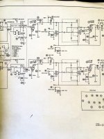
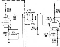
In order to retain the full signal shaping capability of the preamp, you need to break in before the power section, just after switch S6C.
Are you planning on a full preamp-out/amp-in implementation?
In any event, you really need to buffer the preamp O/Ps you are creating. Cascoded DN2540N3-G (TO92 case) depletion mode MOSFET pairs rate to get the job done for you.
Are you planning on a full preamp-out/amp-in implementation?
In any event, you really need to buffer the preamp O/Ps you are creating. Cascoded DN2540N3-G (TO92 case) depletion mode MOSFET pairs rate to get the job done for you.
Attachments
Hi, if I am not mistaken the ST70 has tape switching. You can use the tape monitor jacks for a preamp signal. Here is the description from the EICO manual. I quote from the manual.
"The TAPE OUT1 & TAPE OUT 2 jacks are intended for feeding signal out to the "line" recording Inputs of a tape recorder. These are indedpendent output for channel 1 and channel 2, respectively. They are unaffected by the LEVEL, BALANCE, BASS, TREBLE, HI FILTER, AND LO FILTER controls. "
I guess if you intend to use any of those functions in your signal then another solution like Eli's needs to be considered. cheers.
The problem with the tape recording O/Ps is that they are located immediately after the source selection circuitry. None of the preamp's controls, especially listening level, are available.
I agree with Eli's advice to buffer the preamp output. I've done this in some cases with a simple transistor Sziklai pair (aka reverse-amplified emitter follower or complementary feedback pair) stealing a few mA from the negative grid bias supply. One of the nice things about this approach is that it's easy to design in some gain if you need it for compatibility with the power amps that you're planning to use.
The idea of using the bias supply to energize SS buffering is interesting. Unfortunately, the EICO ST70 uses a 1/2 wave rectified tap on the B+ winding for its bias supply. I'n not comfortable about drawing even a few mA., for buffering purposes, from that sort of circuitry.
I'n not comfortable about drawing even a few mA., for buffering purposes, from that sort of circuitry.
The additional current drain shouldn't trouble anyone because it comes from a tap on a relatively high current winding, but it's certainly possible to make a dog's breakfast out of this by sucking the post-filter voltage way down and/or massively increasing C- ripple. One good workaround would be to make a low-voltage positive supply by adding a second half-wave rectifier diode to the same tap on the transformer. I haven't needed to do that because, so far, I've always found a simple way to steal a few mA from the existing bias supply without messing it up.
One could also build the positive supply and then use it together with the existing negative supply to power an even-better buffer circuit with direct-coupled input. There are many alternate solutions, but I'm not aware of any that just drop into place without having to think about unintended consequences. The closest I ever came to that ideal was when adding monolithic buffer ICs into a PAS-3 preamp. The necessary low-voltage DC power supplies are already present!
I like the additional diode for a positive low voltage rail idea.  No interference, to speak of, with the C- supply is present. 🙂 A SR109 as the rectifying diode would make the new rail switching noise free. That new + rail could be regulated with a LR8 and simple "N" channel JFET source followers would be the buffers.
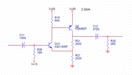
No interference, to speak of, with the C- supply is present. 🙂 A SR109 as the rectifying diode would make the new rail switching noise free. That new + rail could be regulated with a LR8 and simple "N" channel JFET source followers would be the buffers.Here's a buffer-with-gain example design that might be useful. It can be altered to operate on a negative supply rail by simply swapping the transistors. Gain is fixed at 2X (6dB) by using equal-value divider resistors at R21 and R27. Q8 collector should settle around 1/2 of the supply voltage, so Q10 emitter is at 1/4 supply voltage and its base bias is 0.6V above that. Input bias current is around 1uA, so the "V+13" source might need to be adjusted slightly higher. That bias source can drive both buffer circuits. It can be a simple divider off the V+50 rail, with a decoupling cap to ground. There should be plenty of dynamic range even if DC bias conditions aren't perfect, but I recommend 1% resistors at R21 and R27 to insure gain matching across channels. Output coupling cap value is a function of downstream load impedance, of course, but I wouldn't go under 0.47uF.
To make a unity-gain buffer, just short out R21 and replace R27 with a single resistor of 3.9K. The bias source becomes 25V in this case. A minor flaw of the unity-gain case is that oscillation can occur, especially when transistors with good RF characteristics are used along with high bias current. If that happens, just insert a small resistance in series to Q10 emitter. It's unlikely with these transistors at this bias current.
To make a unity-gain buffer, just short out R21 and replace R27 with a single resistor of 3.9K. The bias source becomes 25V in this case. A minor flaw of the unity-gain case is that oscillation can occur, especially when transistors with good RF characteristics are used along with high bias current. If that happens, just insert a small resistance in series to Q10 emitter. It's unlikely with these transistors at this bias current.
Attachments
Not being able to self bias can be an issue with BJTs and enhancement mode MOSFETs. Tubes and JFETs are depletion mode devices and can self bias.
As is frequently the case, more than 1 method will solve a particular problem.
As is frequently the case, more than 1 method will solve a particular problem.
Hello guys thanks for the knowledgeable replies. Mr. Duttman,I've been reading enough of your posts on this site to know I trust your advise, I know you know these old Eico st70's,but sir you far surpass my skill level. I'm sure this would be easy to implement with a schematic with component values. If that's not possible can you recommend a vintage preamp that has a preamp outputs I can duplicate. Thank you very much for your time.
- Status
- Not open for further replies.
- Home
- Amplifiers
- Tubes / Valves
- Eico ST70 needs a preamp output....