tubelab.com said:
The arc theory could be tested easily enough. Simply connect G3 directly to ground, or to its own 10 ohm resistor to ground. If an arc from G2 pr plate hits G3 it won't take out the cathode resistor. If the resistor on G3 blows there was an arc.
That's what I was thinking of doing,but I need to get some more 10ohm R's first.I may have something close in the drawer,will have to look.
I'll go pull the tubes and give them a close inspection,see if I can see anything.
I've always thought Fred's passing was related to his battle with cancer. I'm not 100% sure,Gregg (Geek) knows more.
Either way,he was a great guy,and taught me a lot over the years. (As many of you have, -Thanks to everyone!)
After Fred had passed,my girlfriend (Megan) and I went up to B.C. to meet and visit with Gregg,and pickup the parts for the "RA-100a" that Fred was planning to build.
So,this is it..my rendition of it,and my tribute to Fred.
if you want to use a high plate voltage with cathode resistors you have to lower grid 2 voltage. use a voltage doubler, tied mid-way point to grid two or use a voltage regulator grid 2 voltage should be about 2/3 the plate voltage
good luck
vince oldtubes
good luck
vince oldtubes
Pulled the tubes and inspected them,nothing visible floating around in 3 of them,one had a tiny fleck,of what appears to be mica,it's fairly translucent. So there don't appear to be any grid/cathode 'floaties' in the tubes.
I tried to peer inside the plate structure,with a nice backlight,but couldn't see much.What I did see,appears to be intact,and in good shape.
So perhaps that is a bit of evidence against the arcing theory.
I might connect the 'scope to the grids (with the output tubes pulled) and sit and watch it for a while...see if it drifts/bounces/anything.
KaDe said:Patrick,
what you need with 600 Volt B+ are different toobs !
The only ones that would stand 600V on the screens are KT88.
I think the screens of your EL34 do arcs since they are rated at 425V only.
Cheers Klaus
Not entirely correct. B+ on both is 800V. KT88 screen is 600V, EL 34 is 500V. Something is obviously wrong above this - first off by the poster saying ... the 6L6 schematic calls for -72V and I have EL34s at -76 so it should be underbiased. 6L6 <> EL34. This is the number one newbie error - they see a schematic with a cathode R of 680ohms and assume at ANY B+ that 680 is the right number... This shows that in general the poster doesnt understand bias and how tubes are different.. as such, there could be many unmentioned problems... 50ma per tube wouldn't pop 10ohm Rs... so......... .something else is up.
they see a schematic with a cathode R of 680ohms and assume at ANY B+ that 680 is the right number.
680 ohms?
There is no (large) cathode R here,like in a self/cathode bias setup -except the 10ohm R's,mainly to measure/adjust the cathode current,since this is fixed bias.
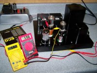
I cranked the bias adjustment pots for the most negative voltage at the grids,which is ~ -80V,If I recall.
I then slowly brought them up to ~25ma (250mV) per tube,measured across the 10ohm cathode R's,just for initial testing. This resulted in approx -76V on G1.
I don't have any 6L6GC tubes on hand (except for some 'questionable' 6L6GB's,and like George said,I'm not about to put those in this amp.)so I used these EH EL34's I have for my ST-70.
I admit I didn't look up the specs on the EL34 before putting them in,I had assumed that they would be OK,since I remembered the Va rating to be in the 8-900V range. If I had seen the lower screen rating,I would have thought twice. -My bad.
However,I wonder how Fred ever managed to run trouble-free with 6L6GC's at these voltages?

50ma per tube wouldn't pop 10ohm Rs... so......... .something else is up.
Exactly,thus my post.I'm kinda stumped,all the voltages check out,and are nice and stable,(including Vg1) with the output tubes pulled.
I just got done 'scoping various stuff..no anomalies yet,that I can find. -there are some funky transients on Vg1 at turn-on,but that's why the standby switch is there I suppose,to give time for the voltages to "settle" and the heaters to warm up.
One other person (oldtubes ?) mentioned that B+ regulation isn't needed for PP operation,since any hum tends to cancel.
That's true,but not my reason for considering it..600V B+ is just too darn high,it seems. If I could drop it about 100V or so (+500V B+) with a regulator ,then the tubes would be a bit happier. Plus everything else in the amp is already regulated (it needs to be since it's direct-coupled.),so why not!

Edit:
I think (oldtubes) also mentioned adding 100ohm R's from each heater wire to ground -I can't,the power meter circuits are powered from the 6.3Vac. Plus,one side of the heater winding is connected to ground.
And for reference,here's "my version" of the schematics. Mostly just cleaned up a bit (removed the preamp stuff, this is just the power-amp.) with a few minor changes,and they also show some of Fred's original "Tweaks and Hacks".
Power Supply
Power Amplifier
Power meter boards
tubelab.com said:
... have used several of those "unknown" chinese 6L6GC's, also without failure at 550 volts and at dissipations far in excess of the specs. The good ones come from the Shuguang factory and are often labeled Sino. The older "Coke Bottle" shaped ones were the best from an abuse standpoint.
+2 on the Shuguang Coke Bottle 6L6GC's being good to the 550 volt range.
The new Tung Sol 6L6GC/STR also looks promising for higher voltages and it seems to be very readily available, and sounds very good. I have attached a pic of these under test in a SimpleSE at about 540 volts across the tube. For reasons unique to my application, I am only running them at about 25 watts dissipation, however.
Based on my experience with the JJ 6V6, I also suspect the JJ 6L6GC could take these voltages, and I have some here for test, but have not got around to it; maybe this afternoon!
Win W5JAG
Attachments
Hello,
this is only my personal opinion, but I think that EH (EL34) and Sovtek tubes are pure c**p!!!
I say so because I had bad experience with both:
about two years ago, me and my friend blew 4( yes, four!!) quartets of EH EL34 tubes in a month. He has an old Hiwatt 100W amp, the fresh tubes initially worked fine, but after a little time (from 1 hour to 1 day), one tube randomly went kaboom with a strong red flash inside the elements and then losing the vacuum. Ouch, lesson learned in the hard way, I'm near to puke when I see these tubes...
 Now we're using Svetlana (winged C after the name problem) and no more problems!
The "new" svetlana production is not good either, I tried them in a unmodified '68 or '69 Laney 100W with about 600V on the plates and screen grids, needless to say, I blew again 2 quartets within a day!! I (partly) solved the problem using a voltage divider to feed the screen grids and upping the screen grid resistors from the stock 470 ohm 5W to 1K 5W
Sorry for the long rant, if it somehow doesn't fit here, please feel free to remove or move
Cheers
Giulio Maiocco
this is only my personal opinion, but I think that EH (EL34) and Sovtek tubes are pure c**p!!!
I say so because I had bad experience with both:
about two years ago, me and my friend blew 4( yes, four!!) quartets of EH EL34 tubes in a month. He has an old Hiwatt 100W amp, the fresh tubes initially worked fine, but after a little time (from 1 hour to 1 day), one tube randomly went kaboom with a strong red flash inside the elements and then losing the vacuum. Ouch, lesson learned in the hard way, I'm near to puke when I see these tubes...
Now we're using Svetlana (winged C after the name problem) and no more problems!The "new" svetlana production is not good either, I tried them in a unmodified '68 or '69 Laney 100W with about 600V on the plates and screen grids, needless to say, I blew again 2 quartets within a day!! I (partly) solved the problem using a voltage divider to feed the screen grids and upping the screen grid resistors from the stock 470 ohm 5W to 1K 5W
Sorry for the long rant, if it somehow doesn't fit here, please feel free to remove or move
Cheers
Giulio Maiocco
Hey Hey you " fireworkers " !
If I had an amp with 600V B+ , I would try some of THESE
I think Trout has collected some experience with the KT77 JJ, shout him a mail to point him to this thread:
email Trout
If I had an amp with 600V B+ , I would try some of THESE
I think Trout has collected some experience with the KT77 JJ, shout him a mail to point him to this thread:
email Trout
With all respect to Mr Nachbauer, I am afraid he simply exceeds too many maximum ratings in this design for reliability.
Maximum specifications are there for a reason, and while voltage specs can sometimes be exceeded if one knows what one is doing, this design is just not on. Yes, some tubes will withstand more, especially anode voltage in tubes with slits between anode pins and the rest in the mounting wafers. But how must one select replacement tubes - try (and blow) enough until one is found that will hold, and for how long?
Anyone trying to get 100W (after OPT efficiency) out of a pair of 6L6GCs or EL34s, especially with UL topology, can forget it. On the g1, g2 mounting rods just above the bottom wafer, there are nicks to facilitate location. The sharp protrusions caused by these are only 0,69mm apart in a 6L6GC from GE. At maximum negative signal swing on g1 and with g2 OPT taps at 43%, the peak voltage encountered here will be 925V. If that is on, why would slits be cut in wafers round anode pins more than 18x the above distance away from everything else, to tolerate the voltage?
Voltages are not given, but if maximum heater-cathode voltages in the 12AT7 and 6BG6 are not exceeded (their heaters are fed from the same source), the h.t. over the 12AT7 plus load resistor is 615V. The cathode-anode voltage will obviously be lower, but the design is still dangerous for a tube with maximum Vc.a rating of 300V.
As an aside, d.c. for the 12AT7 heater by an unsmoothed half-wave doubler?? There is every chance that straight a.c. on the heater will be quieter.
Apology for the criticism (not aimed at Mr Nachbaur, just this design!) .... I cannot suggest a reason for the cathode resistor failure, but would suspect g2-g1 d.c. interference, It might not be all that visible as fireworks; one must remember that g1 sits at a high resistance point and any leakage could do the necessary. Like others I would suggest looking at the EL34 cathodes with a storage facility so that the effect can be stored for analysis. But the design would still be unreliable. (Also, I would suggest a higher resistor, say 1K, in parallel with the present low cathode resistor, so as to protect the c-h insolation every time the main resistor is popped. When that happens as per now, the 6L6 cathodes could be pulled up to dangerous voltages.)
Again apologies for the criticism, I cannot see 100W reliably coming out here without a pair of tubes either side op push-pull and then lower d.c. voltages. I have worked this several times in the past and .... no - not reliably.
Edit: Or then the KT77.
W5JAG
I bet that's your callsign. Does your XYL know you steal her meatloaf tins to make PSU chassis?
Shame on you...
GM1TDU aka Stentor
I bet that's your callsign. Does your XYL know you steal her meatloaf tins to make PSU chassis?
Shame on you...
GM1TDU aka Stentor
No need to apologise as far as I'm concerned, Johan. I also agree that the design is poor, partly because the power expectation is completely unrealistic and the voltages are too high, as you say; but also because I can see potential pitfalls and no compensating benefits in the crazy LTP and CCS design.
As a matter of fact, I use an LTP splitter with pentode CCS too, but it's simple by comparison and I wouldn't dream of direct coupling it to an output stage.
As a matter of fact, I use an LTP splitter with pentode CCS too, but it's simple by comparison and I wouldn't dream of direct coupling it to an output stage.
As a matter of fact, I use an LTP splitter with pentode CCS too, but it's simple by comparison and I wouldn't dream of direct coupling it to an output stage.
Can you share the schematic?
Hmm.
Okay, so the first issue is the high B+ voltage. I'm thinking about adding some resistance in there,to help lower it a bit (maybe increase that 10ohm resistor.)
Also,I think a regulator might be a good idea,to help drop some voltage.
I'm also considering going to Pentode,or perhaps Triode connection,if I can find a suitable set of tubes to use,and drop/regulate the B+ (and Sg2) voltage to a suitable amount.
Does anyone have any suggestions for B+ regulator circuits?
Patrick
I remember well this "pop" noise from the speaker together with a "yellow shine" in the valve from my own experiments when I did exceed rated screen voltage limits too much. This is arcing from grid2 to grid1 and from my experience the valve is lost, it will arc again the next power up.
The small 10 Ohm cathode resistor is mainly to protect the output-transformer, not the valve.
Before you consider any changes to the original circuit ( I like it ) make sure to get a new quad of suitable output valves on hand.
I have been using 6CA7, EL34, 6L6GC, 6550A, 7027A, 8417 up to 500V B+ in UL-mode with no problems so far, but would never torture them with 600Volt B+.
KT88´s will suck too much heater current, what remaines to try is a KT77.
You will need a new valve set for your ST-70 anyway.
Cheers
Klaus
I'm not able to post it right now but it's very similar to the pentode current sink shown in Morgan Jones's Valve Amplifiers. There's a potential divider that raises the voltage of the control grid, which enables a higher value resistor to be used in the cathode, thereby raising the effective impedance of the pentode and making it closer to being a true CCS.Can you share the schematic?
The pentode I use is a 6AU6, acting as the tail of a 6SL7 LTP splitter. The 6AU6 is operating at 2 mA plate current, wth 100v screen-cathode and 105v plate-cathode. 125v and 225v respectively would be even better but, even at this operating point, the plate curve of the 6AU6 is almost horizontal. The amp is all-differential design, with the 6SL7 LTP splitter as its input stage. The 6SL7 grids are at ground potential, so, of course, there has to be a negative supply for the 6AU6 to operate.
More Torture Testing!
So,I got some chinese 6L6GC tubes from Mikkel (mcs),and plugged them in the amp.
I am unsure of the make? Perhaps Mikkel will chime in.
B+= ~650V loaded. (unloaded it's ~740V!)
Bias current is about 45-55ma per tube.(Just the rough initial adjustment to get them 'close enough'.)
At 50ma (32.5W) they just start to show a slight bit of color along the fins. At 55ma they are blushing a fair amount.
I have also removed half of the filtering capacitors in the B+ supply.
So,now we're down to 23.5uf->5H->110uf,in an attempt to lower the B+ voltage a bit. I'm not sure it's helped.
I need to find a smaller film cap to try as the first C position.
Also,a small note; I moved some of the stuff around on my photobucket site,so some of the other links are dead. All of my RA-100 pics,schematics,etc. are here: RA-100 Stuff
And the growing thread on GZ: GeekZone
- Status
- Not open for further replies.
- Home
- Amplifiers
- Tubes / Valves
- EH EL34's at +600V?