Hi everybody,
First of all, sorry for the weird title but english is not my mother langage and besides I don't know how to describe it otherwise.
I'm trying to understand how this circuit works, especially the preamp. Could not find any answer to my question yet.
Let me explain :
I understand that the first half of the op-amp makes a bandpass filter, althought the values are quite strange for a bass preamp. My problem is about the path of the second feedback loop which puts in series C5//R5, C4, R4, R3//C3, R8 and C9.
In this case, how to know which frequencies are filtered at the output 1 of the op-amp ? If the second half was non-inverting, I would read two bandpass filter put in series, but here the second feedback loop is refered to ground through the first one... So the classic formula 1/(2piRC) can't work. Or am I wrong somewhere ?
Futhermore I read in Teemu Kyttala's Solid State Guitar Amplifiers (p210) that :
[R2] is extremely important in cases when the feedback loop’s connection to reference (or common) through [R8] is also capacitor coupled. [R2] (along with other parallel impedances) also sets the input impedance. To prevent the bias currents of the input from interfering with the offset voltage the value of [R2] should ideally be equal to parallel connection of [R8] and [R3].
(I changed the name of the resistor to fit this schematic)
This is not what I see neither. So what the heck ?
So if you have a clue of what is going on here or know where I could find an article or a bit of an explanation somewhere, I would be very grateful.
Cheers✌️
Attachments
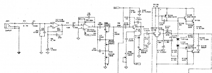
Not in a feedback loop, its a frequency-dependent potential divider on the output of the opamp.the second feedback loop which puts in series C5//R5, C4, R4, R3//C3, R8 and C9.
Both opamps are configured as gain stages with relatively flat response in the audio band. The RC rollovers are at 16Hz and 100kHz, ie subsonic and ultrasonic. 16Hz is a bit high, it will eat into the subbass response a little, but to a first approximation both opamp stages are providing flat gain.
The tone control iself is passive, just the divider section - its a fairly complicated network, simulation is the easiest approach to figuring out its reponse I suspect unless you can find that circuit in a textbook somewhere.
Wow ! Thanks for the fast reply Mark !Not in a feedback loop, its a frequency-dependent potential divider on the output of the opamp.
Both opamps are configured as gain stages with relatively flat response in the audio band. The RC rollovers are at 16Hz and 100kHz, ie subsonic and ultrasonic. 16Hz is a bit high, it will eat into the subbass response a little, but to a first approximation both opamp stages are providing flat gain.
I still do not get how you calculate the 16-100.000hz in that case. Again I'm stuck with the classic 1/(2piRC). It does not apply if I follow you...
The tone control is explained many times on the web, complex indeed, but widely commented.