The problem is not that the delay changes with frequency so much as the AC is not a single physical position. [/IMG]
True. In this case those things are pretty much the same, though. For this speaker what mattered was the delay differences; knowing the exact position of the AC was less relevant.
I'm glad you asked. The main example that springs to mind is any large(ish) dual cone driver whose mechanical crossover between cones works as intended.True, but first, show me a driver for which the phase a the measurement point can not be reduced to minimum phase.
There is no way I can see that a driver of that type could be minimum phase at high frequencies, and the ones I've measured certainly are not.
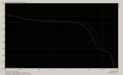
Image 1 is excess phase of two 8" dual cone full range drivers. Red is a Fostex FE207E, yellow is a Coral Flat 8 II, both measured 1 metre on axis. Both have the same 3.9ms window time and same delay time estimation for absolute phase.
The total delay estimation relative to microphone distance agrees very closely (within 10mm) with my previously estimated acoustic centres of the drivers, and the calculated (hilbert) minimum phase response tracks parallel with actual phase up to ~2Khz before diverging, so I think I have the absolute time delay fairly close in this measurement.
I find the difference in excess phase between the two drivers quite interesting. Both have a 160mm main cone, but the Coral has a 80mm curvilinear whizzer with a 30mm aluminium dust cap directly attached to the VC former, while the Fostex has a 60mm conical whizzer with a 35mm paper dust cap attached to the whizzer paper.
Prior measurements of a very similar Coral missing its dust cap and later missing its whizzer cone show that the main cone rolls off quite steeply at about 6Khz, the whizzer cone rolls off gradually at around 12Khz, and the dust cap rolls off at about 16Khz, all of which seems to fit in nicely with the observed excess phase. There should be a mechanical crossover between the two cones at ~6Khz, but there may also be a second mechanical crossover between the whizzer and radiating dust cap somewhere around 14Khz as well, as the kink in excess phase suggests.
On the Fostex it would appear that the crossover between the two cones is quite a bit higher in frequency ~8Khz, and the fact that there is no significant kink between 10-20Khz (and the fact that the Fostex has much inferior response in this region) suggests that the dust cap is not independently radiating and just forms a part of the whizzer cone...
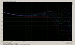
Image 2 is 0.01ms increments in the phase delay estimation for the Coral driver, there is no distance where it can be reduced to minimum phase, the closest you could get by just adjusting the delay would still leave a +/-30 degree variation.
I suppose you could argue that a dual cone driver is really a coaxial 2 way design which just happens to share a voice coil, which is true, but at the end of the day its still just a single driver with a voice coil and some type of cone structure attached to it, so I imagine that non minimum phase would be possible for some more exotic designs as well, and in fact that any time a driver is large in wavelengths and non piston in operation there is at least the potential for a non minimum phase response to occur at high frequencies, even if it doesn't generally work out that way.
All of this just serves to further illustrate what a nebulous concept acoustic centre is mind you... it's a virtual source not a real one, and it's only valid or useful within certain limited constraints.
Attachments
Last edited:
I've often seen simplistic articles on speaker design quote the acoustic centre of a driver as being "roughly" at the voice coil/gap, but that's nonsense because measuring the acoustic centre back from the microphone assumes that the entire path length was through air, which it isn't.Yes. The unusual thing is that on some given axis, say on-axis for simplicity, this appears to be the case. Every test I made indicates that this point is somewhere slightly in front of the point of attachment of the former to the diaphragm for dynamic drivers. Unusual in that it is not a physical point on the driver. What I cannot deduce is how this can occur, yet the match of measurement to model seems to satisfy the requirements in this specific case. Conjecture might be that it has to do with how the wave coalesces as it moves outward from the individual points on the diaphragm surface.
At the very least you always have the signal propagation from the voice coil through the vc former to the point of attachment on the cone before it reaches air - for this entire distance the wave is travelling much faster through a solid medium, (in fact in the vc former it must be travelling as a compression wave) so the apparent acoustic centre will come forward. The distance from the vc gap to the centre of the cone more or less doesn't count, because it contributes so little delay.
As for why it can measure in front of the centre of the cone, I think you answered your own question below 🙂
As far as my understanding goes, that's exactly the reason why the acoustic centre on some drivers can be ahead of the dust cap - the wave travels faster through the cone than through air, and if the forward vector of the wave travelling through the cone is also faster than the speed of sound in air, (the cone angle is steep enough for the cone material) the earliest launch point could be at the perimeter and reach the listener before the part of the wave launched from the dome. When integrated it would bring the effective acoustic centre further forward than the centre part of the cone.That is logical on initial consideration, but then there's the puzzling consideration that one would initially think that it must be at the earliest launch point of the wave, that is, at the attachment point of former to diaphragm. Until one considers that the impulse moves faster in the diaphragm than in air, so then there's the consideration of time delays through air vs. shorter time delay through the diaphragm. Coupled with geometry, it seems quite possible that the first portion of the output to reach a mic might actually be from the rim of the diaphragm if the speed of sound in the diaphragm is significantly faster than it is in air. Then add in that the wave is progressively launched all along the diaphragm in concentric rings (for axial measurement), complicated by wave coalescence (if this is a factor, I can only make conjecture here).
However I would consider this to be a badly designed driver - at least if it's attempting to operate at high frequencies, and isn't just a woofer or <2Khz mid bass.
To launch a coherent wave front at high frequencies where a driver is large in wavelengths (eg a largish full range driver) the angle (and depth) of the cone has to be matched to the velocity of propagation through the cone material so that the wave from all parts of the cone arrive at the listener at the same time. (The directly forward vector of the wave velocity through the cone is equal to the speed of sound in air...)
If you do this, (and get everything else right) you can get a flat on axis response (at least in theory) even at frequencies where the cone is many wavelengths across. If you make the cone too shallow or too deep you'll get periodic peaks and dips in the on axis response that you cant fix in any other way.
Too deep a cone and the wave from the edge arrives first, too shallow and the wave from the edge arrives after the wave from the centre area.
Interestingly of the two full range drivers I quoted in my previous post - they both have quite different main cone angles. The Coral is moderately deep while the Fostex is quite a lot shallower, despite the paper being very similar looking composition and thickness, and probably having much the same propagation velocity.
Funnily enough the Fostex driver has tell-tale periodic peaks and dips in the response from about 2.5Khz to 6Khz that you would expect from a non-coherant wavefront launch, while the Coral does not have those ripples. I guess someone at Fostex screwed up... 😉
On some drivers at least, I'd agree, what looks like breakup also includes interference patterns due to the geometry as I described a moment ago. These are of non-resonant nature, (there's no energy storage involved, just a spread out arrival of the impulse due to unequal path lengths...) which might explain why the ragged looking frequency response of some full range drivers actually sounds a lot better than it measures. Peaks and dips from uncontrolled cone breakup on the other hand, sound bad.On this I would agree, unless, of course, it goes back to how the wave may coalesce. Does the wave at any given single frequency show some time distributed output or does it reduce to a single point in practice? The fact that drivers show non-linearity due to geometry as the geometry becomes a significant percentage of the wavelength indicates that although the response is an integration over the surface, it's vectoral in nature, hence the interference patterns we see that are sometimes considered to be breakup (not wanting to divert the topic here, however). Change the axis and that "breakup" often goes away in some cases. Similar issue, I think. Last comment on that for me in this thread!
You pose many interesting thoughts in the rest of your post but I'm not sure that I know enough to respond to them in a meaningful way.... 🙂
Last edited:
I've often seen simplistic articles on speaker design quote the acoustic centre of a driver as being "roughly" at the voice coil/gap, but that's nonsense because measuring the acoustic centre back from the microphone assumes that the entire path length was through air, which it isn't.
Not nonsense at all. The term "roughly" implies a generalization. As you point out the speed of sound through cone material is faster than in air and it works out that the cone body angle is about right with most drivers to give a forward vector near the speed of sound.
For this reason the acoustic center of a driver is "roughly" at the voice coil.
Where is this discussion going? The primary reason for discussing acoustic center has to do with allignment between two drivers in a multiway system. Whether we consider acoustic centers or merely deal with phase allignment through the crossover region we can easily achieve desired results on axis. When moving off axis we would ideally like the time offset to remain constant. In practice the greater issue is natural driver rolloff off axis impacting what might be a good crossover blend on axis. Lack of a compact and defined acoustic center for all angles is not the big issue some would imply.
David S.
Start Correction etc
Expanding on some excellent points that othes have raised, it "seems" to me that this is a "sort of" inverse situation to End Correction, as in ports. Whereby due account of it should be taken into consideration when calculating the length of a port/s & the like. That's why i've called it "Start Correction" for help in determining AC.
Also, the more a cone/diaphram is displaced in either direction, the further it will move away from it's intital AC. Which will lead to increasing phase shifts etc, i would have thought. Which means, the more SPL you have the worse things can get, in this respect.
There is no net displacement of the acoustic centre at high frequencies from low frequency excursion though - because you're deflecting equally each way on each half cycle. What you do get is frequency modulation (and therefore phase modulation) of the higher frequencies due to the low frequency displacement though...Also, the more a cone/diaphram is displaced in either direction, the further it will move away from it's intital AC. Which will lead to increasing phase shifts etc, i would have thought. Which means, the more SPL you have the worse things can get, in this respect.
Ones you have build a crossover for the driver and it replicates acoustically a certain bandpass, say a L/R4 , it´s getting more easy.
As I said, it is really academic and not very relevant to design. Example, for an MTM where is the AC of the M-M? It doesn't matter because when aligning the tweeter all we care about is how much we have to offset the tweeter to sum correctly with the M-M at the design position. Where the AC for each M driver is or may be is of little concern.
It's like, move on.....
It's like, move on.....
While it's not an actual physical location, and its position is a little bit indeterminate depending on how you try to measure it, can shift a small amount with frequency, movement of the listener off axis etc, I disagree that it's not relevant to design or only of academic interest.As I said, it is really academic and not very relevant to design.
I don't buy the whole "mount drivers without worrying about their acoustic centres, measure their individual phase response at the design point and design the network to suit" philosophy.
As an exercise in achieving phase tracking and amplitude summing at the design point that approach might be valid, but it's not completely equivalent to physically time aligning the acoustic centres of the two drivers in the z-axis.
In a passive design a pure time delay is not an option, and more than a small amount of all pass delay in the overlap region is not very practical or economic of components, so you're left with approximate phase correction at best.
However even if you go as far as an active crossover with a DSP based pure delay to correct z-axis time alignment there are still two differences from doing it physically - (1) the result will be different off axis, because an electronic time delay can only be correct on the chosen design axis and will over-correct off the horizontal axis, and (2) inverse square law fall off of the two drivers won't track with each other accurately if one driver's acoustic centre is significantly closer to the listener, causing changes in the balance between the two drivers with varying distance, even staying on the design axis.
You could argue that such effects might be relatively small on small speakers where the z-axis error is small, and that you can get a "good enough" result by bending the phase shift of the network to approximately compensate for the phase shifts of the physical offset, but on anything larger (such as combining horns and direct radiators, or a shallow tweeter combined with a deep wide range driver) where you have large z-axis offsets and/or high crossover frequencies relative to the z-axis error you can't just ignore the acoustic centres.
I'm not sure I see the relevance of this to the discussion about the acoustic centre of individual drivers ? How is the individual acoustic centres of two M's in an MTM relevant ? You're just introducing a scenario that was outside of the original discussion, because now you have a weird compound driver that is made up of two physically displaced drivers whose virtual acoustic centre is outside of both drivers...Example, for an MTM where is the AC of the M-M? It doesn't matter because when aligning the tweeter all we care about is how much we have to offset the tweeter to sum correctly with the M-M at the design position. Where the AC for each M driver is or may be is of little concern.
But even in this case you're saying you need to know how much the tweeter needs to be offset to sum correctly - surely the whole point of finding the approximate acoustic centres, or more importantly the relative acoustic centre offset of the two drivers.
Last edited:
Why it is so complicated ? It is physical ? no ?
I like a lot Wolf's pictures from his blog, simple and efficient for who wants determine AC.


In fact only the difference between the two drivers is important. What I can say, smaller is the difference, easier to do the crossover.
I like a lot Wolf's pictures from his blog, simple and efficient for who wants determine AC.
In fact only the difference between the two drivers is important. What I can say, smaller is the difference, easier to do the crossover.
I don't buy the whole "mount drivers without worrying about their acoustic centres, measure their individual phase response at the design point and design the network to suit" philosophy.
As an exercise in achieving phase tracking and amplitude summing at the design point that approach might be valid, but it's not completely equivalent to physically time aligning the acoustic centres of the two drivers in the z-axis.
What don't you buy about it, since in practice it works so well?
For those that design systems via simulation (xopt, leap crossover shop, etc.) there have always been only two approaches to setting up a simulation.
1) Set a mic some distance from the baffle (1 or 2 meters). Measure response and phase of various sections. Subtract out the air path delay, if you wish, to the baffle distance. Retain the phase difference between drivers in the measurements. Define the system geometry as having the acoustic centers in the center of the driver but on the baffle surface. Design a network that works with that scenario.
2) Set a mic some distance from the baffle (1 or 2 meters). Measure response but not the phase of various sections. Hilbert transform the frequency response. Apply the calculated phase to the drivers. Define the system geometry as having the acoustic centers in the center of the driver plus ascribe a depth equivalent to the recess of the acoustic center. Design a network that works with that scenario.
So how do you know the depth of the acoustic center? LEAP will tell you to figure out the distance from the baffle surface to the center of the voice coil (since their measuring system will not measure phase).
The second approach works in practice but I find that I make fewer errors with the first. Obviously, the only way to use the second approach and know that you got the acoustic center correct is to measure phase and compare measured phase to the Hilbert transform of frequency response, at which point you might as well use the first approach!!
Do I care where the acoustic center was?
The first question is whether I intend to have a stepped baffle or a flat baffle. If the answer is a flat baffle the depth of the acoustic center is something I can't change and must deal with. I am back to having to "mount drivers without worrying about their acoustic centres, measure their individual phase response at the design point and design the network to suit". There is absolutely no way around that.
If I intend to offset the baffles then I would probably want to line up the acoustic centers. Still, I can only get the system to work if I have a crossover scheme that works with the no delay case. i.e. it deals with driver delay from limited bandwidth and the delay of the networks. This is a chance to use the ideal crossover schemes that add up to linear phase (yes, first order, sigh!), as long as I achieve total acoustical response that matches the targets. If not I will need to correct with further shifting (acoustic centers no longer in line) or networks that adjust for delay discrepencies (back to arbitrary network compensation).
If I'm using DSP then this is all pointless as I can delay either by the ideal amount or just fudge delay until it works.
I still think the only interesting question is how the delay between units varies off axis, but it is still secondary to the off-axis response degradation.
David S.
I have an idea. Mount a tweeter and a woofer on separate baffles without crossover. Put the microphone on the axis you want to study. Reverse the polarity of the tweeter. Push it so far back that you get maximum cancelation over the widest possible frequency range.
Hi Dave,What don't you buy about it, since in practice it works so well?
For those that design systems via simulation (xopt, leap crossover shop, etc.) there have always been only two approaches to setting up a simulation.
1) Set a mic some distance from the baffle (1 or 2 meters). Measure response and phase of various sections. Subtract out the air path delay, if you wish, to the baffle distance. Retain the phase difference between drivers in the measurements. Define the system geometry as having the acoustic centers in the center of the driver but on the baffle surface. Design a network that works with that scenario.
2) Set a mic some distance from the baffle (1 or 2 meters). Measure response but not the phase of various sections. Hilbert transform the frequency response. Apply the calculated phase to the drivers. Define the system geometry as having the acoustic centers in the center of the driver plus ascribe a depth equivalent to the recess of the acoustic center. Design a network that works with that scenario.
So how do you know the depth of the acoustic center? LEAP will tell you to figure out the distance from the baffle surface to the center of the voice coil (since their measuring system will not measure phase).
The second approach works in practice but I find that I make fewer errors with the first. Obviously, the only way to use the second approach and know that you got the acoustic center correct is to measure phase and compare measured phase to the Hilbert transform of frequency response, at which point you might as well use the first approach!!
Do I care where the acoustic center was?
I don't think you quite got what I was getting at, my point was not so much that the above design approach is "wrong" as such, clearly it works in terms of achieving a desired phase and amplitude response. (within a certain margin of error anyway, since simple phase correction of a time delay induced error can only be approximate, even on axis)
My argument is that creating a design which has large (relative to crossover frequency) errors in z-axis alignment of acoustic centres due to flat baffle mounting is inherently a compromise, and that using the above design methodology is just a case of "making the most of a bad situation", not an optimum no-compromises approach.
If a particular designs constraints dictate a flat baffle, that's fine, you work within those limitations and get the best result possible by getting the best phase tracking and amplitude response you can, however I would argue that just because the amplitude response might measure ok and the phase might track within an acceptable margin doesn't make it as good or equivalent to actually aligning the drivers, and obviously the step and impulse responses will be very different unless you use a pure delay in the compensation.The first question is whether I intend to have a stepped baffle or a flat baffle. If the answer is a flat baffle the depth of the acoustic center is something I can't change and must deal with. I am back to having to "mount drivers without worrying about their acoustic centres, measure their individual phase response at the design point and design the network to suit". There is absolutely no way around that.
A stepped baffle can introduce compromises of its own with diffraction of course, and that is the trade off, (along with complexity) but that can be largely mitigated by using drivers with some directivity control IMHO, which would have also helped to mitigate the diffraction you'd get from the edge of a normal non-stepped baffle anyway. (Particularly for the tweeter)
(In practice I would only bother to step the baffle between a midrange and tweeter, between a woofer and midrange the phase error wouldn't be enough to be worth the trouble)
If you're designing the crossover from scratch for the stepped baffle, I don't see how this is any more difficult than designing a crossover from scratch for a non-stepped baffle design ? Surely it's easier in fact... especially since once you have a stepped baffle you always have the option to "dial in" a small deliberate error in the z-axis alignment as an additional variable to adjust to get the phasing just right.If I intend to offset the baffles then I would probably want to line up the acoustic centers. Still, I can only get the system to work if I have a crossover scheme that works with the no delay case. i.e. it deals with driver delay from limited bandwidth and the delay of the networks.
I'm not suggesting that the acoustic centres have to be perfectly aligned - given the ambiguity in determining them and the fact that they can shift with frequency that's probably not possible. But if you can keep phase shift error due to offset at the crossover frequency less than say 45 degrees you make life much easier for yourself.This is a chance to use the ideal crossover schemes that add up to linear phase (yes, first order, sigh!), as long as I achieve total acoustical response that matches the targets. If not I will need to correct with further shifting (acoustic centers no longer in line) or networks that adjust for delay discrepencies (back to arbitrary network compensation).
I agree that that's an interesting question, and one thing is for certain - the delay variation between units as you go off axis will be different with a stepped baffle physically time aligned design than one which achieves it's time alignment with a DSP delay...the two are not equivalent.If I'm using DSP then this is all pointless as I can delay either by the ideal amount or just fudge delay until it works.
I still think the only interesting question is how the delay between units varies off axis, but it is still secondary to the off-axis response degradation.
Last edited:
The discussion is getting too esoteric for me. Anyone who designs loudspeakers know how to compensate for offsets and determining where the AC is typically does not enter the picture. Several years ago I was very much into transient perfect designs and successful at it. Never once have I bothered to try to find the AC. I always measure phase relative to some fixed reference point; the plane a tweeter face plate or woofer mounting flange. Form that any relative offset is easily determined. This is not done with a fudge, it is a precise calculation of the required off set or digital delay.
Did the linear phase speakers you have being so successful with sound any better that the ones with an all pass you make now ?
I have an idea. Mount a tweeter and a woofer on separate baffles without crossover. Put the microphone on the axis you want to study. Reverse the polarity of the tweeter. Push it so far back that you get maximum cancelation over the widest possible frequency range.
This doesn't work. Once the crossover comes in, or you use some kind of EQ on the drivers, everything is messed up again.
I haven't tried it yet, but I think the following might work:
Measure the reponse and phase. Calculate the minimum phase (Hilbert Transform). Put the marker in front of the impuls and try and get the measured phase tot track the minimum phase as good as possible. Then you know the absolute delay from AC to mic. You don't yet know exactly where the AC is, but at least you know the delay difference between the drivers you have measured. Then you can change their relative positions to align the AC's.
Good idea ( Babbage´s Differential Engine ? ), but that is what i say, with crossover it´s different.
A) I could not draw the conclusion re does transient perfect sounded better because there were too many other variables. But with the Ultimate Equalizer I can design a system which is identical in every way except linear vs. nonlinear phase and it would be hard to say that in general linear phase is better. There seems to be a difference in the low frequency if any at all.
B) Regarding offsets. I measure the drivers with phase relative to the mounting flange. Then I do my simulations. After that I can build (or set up) the x-o and measure the response of each driver at the design point. From that the inter driver phase difference at the x-o frequency can be determined and compared to what it should be for the specific type of x-o. Knowing the difference between the target phase difference and the measured phase difference gives me the amount of phase error which can then be directly converted to the required offset of delay.
Take a look at the bottom 3 figures on this web page.
Notice there is no mention of ACs or minimum phase.
Last edited:
John, i was there in 1993. We build a digital speaker in Essex that could be switched from linear phase to 4th order allpass. With some artificial signal like short pulses, one version sounded "click-click" and the other "clock-clock". With music the effect was lost. Very linear frequency response and off axis radiation pattern emerged as the most important parameters, of cause with good dynamic range and low distortion.
Nevertheless i listen to phase linear wideband drivers. Not the stuff you might know like Lowther and such. Mine is plus-minus 1dB on an octave to octave basis, 1/6 oct. smoothed, extended to over 20kHz, analog equalization, high sensitivity. I prefer it to multiway, but maybe out of other reasons. Except the Essex system where we build everything ourself, even the DSP and the DA converters not to speak about the cables, i never heard a digital system that had even remotely the fine dynamics. But when have you a team of one Professor, 3 PHDs, two engineers and one designer totally obsessed with sound quality ? This back and forth switching on a low key computer based DSP does not cut the mustard. Anyway, our research and others did not change the situation a jota. Commercial speakers got worse the last 20 years. Everybody is searching for that magic transfer function that makes the damn junk sell. That is one of the reasons i spend so much time here with "amateurs". Amare is latin and means love.
Nevertheless i listen to phase linear wideband drivers. Not the stuff you might know like Lowther and such. Mine is plus-minus 1dB on an octave to octave basis, 1/6 oct. smoothed, extended to over 20kHz, analog equalization, high sensitivity. I prefer it to multiway, but maybe out of other reasons. Except the Essex system where we build everything ourself, even the DSP and the DA converters not to speak about the cables, i never heard a digital system that had even remotely the fine dynamics. But when have you a team of one Professor, 3 PHDs, two engineers and one designer totally obsessed with sound quality ? This back and forth switching on a low key computer based DSP does not cut the mustard. Anyway, our research and others did not change the situation a jota. Commercial speakers got worse the last 20 years. Everybody is searching for that magic transfer function that makes the damn junk sell. That is one of the reasons i spend so much time here with "amateurs". Amare is latin and means love.
And why would that be? You have some specific technical details on which to base this judgement I presume?This back and forth switching on a low key computer based DSP does not cut the mustard.
Dave
- Status
- Not open for further replies.
- Home
- Loudspeakers
- Multi-Way
- Effective acoustic center redefined