Hi folks,
today a bit more theoretical than usual.
Given that amplifiers are delicately compensated for a choice of bandwidth, slew rate, overshoot, one is (should) be concerned a bit when substituting transistors. Especially when working on an older design and original parts are no longer available (for comparison) and one does not want/is able to rework the compensation.
Think of a general 3 stage amp (input differential, VAS, outputstage without gain).
Since speed (slew rate) is determined by the VAS and not by the output stage I come to my first thought:
Assume there is no feedback taken from the output stage back (to whereever), substituting a 30MHz bjt for a 3MHz bjt in the gainless output stage should not affect stability, nor other parameters?
Next, a bit more tricky: reworking the VAS. The 15MHz 2N5416 is maybe a nice part, but close to 40 years old. Replace that old guy with say a 200MHz 2SA1360.
Given that the frequency compensation around the VAS is done properly, I would believe that this should also not affect stability.
Why?
As far as I understand Bode-analysis, the poles and zeros of the loop gain determine stability (+ compensation), thus as long as the new transistor has a similar gain, stability should be conserved, since the gain is anyway 0 after a certain frequency. Of course this assumes comparable parasitic capacitances and means also that VAS slew rate is unchanged by this substitution. Only remaining advantage slightly lower (non-linear) Cob (?) and better linearity.
Any inputs greatly appreciated guys!
Heat up the solid state section here, so that we have a nice discussion! Benefits all, it's always hard to get elaborate replies on such questions.
Have fun, Hannes
------------------
To name the beast, I'm talking about the Cello Encore amp, schematic is
http://www.nasotec.co.kr/acecart/bin/boarddata/DataRoom/114.pdf
discussion was here
http://www.diyaudio.com/forums/showthread.php?s=&threadid=116237&highlight=
In case you want to dig a bit into the workings of this amp, you can use Steven's enlightening analysis as starting point
voltage clamp
http://www.diyaudio.com/forums/showthread.php?postid=1420539#post1420539
http://www.diyaudio.com/forums/showthread.php?postid=1421533#post1421533
current mirror in VAS, cascode
http://www.diyaudio.com/forums/showthread.php?postid=1421545#post1421545
output stage
http://www.diyaudio.com/forums/showthread.php?postid=1424115#post1424115
simulation of that amp is a bit wonky, so better rely on general principles.
Hannes,
this amplifier has some qualities.
What parts are you having on hand? What are the rail voltages? Are you driving full range speakers?
All the amplifying devices have poor electrical and sonic properties, heavy, deteriorating phase compensation.
The proposed goal would be: linearizing the stages, lowering the open-loop gain, extending the bandwidth.
Hi Lumba,
thanks for your kind words, I'm indeed still working on this amp.
I'm not sure what you exactly mean with bad sounding transistors, the input jfets are very nice parts, the drivers are also great standard parts, even the big outputs were first class for a long time. Do not forget, this design is from '88!
Parts wise I will run it with the nice MJW0281A/MJW0302A in the output and more spicy VAS-transistors (therefore the original posting), likely Toshibas 2SA1360 or some nice Sanyos. By the way, the original 2N5416 are commonly used, also in the leach-amp.
From what I know now the stability will be affected by at least the VAS-transistor change (due to lower Cob), but this can be easily fixed by Miller-compensation if needed at all.
Well, regarding frequency compensation: it's only lead and lead-lag compensated (except outputstage), which have better performance than simple Miller-compensation.
All the best, Hannes
PS: by the way, I have yet to fully understand one of your circuits - they are a bit like riddles! I would not have thought that you're a fan of such unusual and rather complex amps!
Hannes,
listen, the parts have to be selected very carefully. I have only looked at the voltage amplifier section (114pdf), we should forget about the original design, those many capacitors make me feel sick. The question is what can be implemented practically. The suggested input stage would fit easily, except the current mirrors.
OK, keep U403 (until you are able to buy some much better Toshiba JFETs), but use 2SC3423/2SA1360 instead of 2N6718/2N5416.
The VAS stage is somewhat peculiar, I do not know the idea behind it, but I am extremely suspicious about that kind of trickery - could be converted to decent cascode.
I would make an experiment with bypassing the VAS.
Have you measured the rail voltages?
Hi Lumba,
I was made aware that this peculiar differential-VAS combination was also used by Bob Cordell in his 1984 AES paper, where he published an error-correction amp. With this special frequency compensation the frontend achieved a slew rate of stunning 300V/mus! Pretty impressive.
I feel the U403 is perfectly used here, as the higher transconductance parts from Toshiba would give higher gain and therefore would lessen the need for a VAS. Would question the concept, IMHO. However I have the parts on hand, so don't worry that I wouldn't use them if necessary.
By the way, I've no exact rail voltage, but it is easily calculated from the spec'd output power 100W/8R, so about 35V.
Mmmh, do you have doubts that I won't try my best 😀
The largest problem I see is to readjust the frequency compensation back to optimum performance after the parts substitutions. So I think it's a question wether one wants to stick close to the original design (all parts original except the 2N6718 which is obsolete, but easily replaced) and get the exceptional performance for free, or stick in new transistors and build a power oscillator.
Currently my pcb-layout gives both options.
Every input greatly appreciated, Sir.
All the best to gamla stan, Hannes
PS: I can send you Bob Cordell's paper if you don't have it, otherwise it's online as well.
I was made aware that this peculiar differential-VAS combination was also used by Bob Cordell in his 1984 AES paper, where he published an error-correction amp. With this special frequency compensation the frontend achieved a slew rate of stunning 300V/mus! Pretty impressive.
I feel the U403 is perfectly used here, as the higher transconductance parts from Toshiba would give higher gain and therefore would lessen the need for a VAS. Would question the concept, IMHO. However I have the parts on hand, so don't worry that I wouldn't use them if necessary.
By the way, I've no exact rail voltage, but it is easily calculated from the spec'd output power 100W/8R, so about 35V.
listen, the parts have to be selected very carefully.
Mmmh, do you have doubts that I won't try my best 😀
The largest problem I see is to readjust the frequency compensation back to optimum performance after the parts substitutions. So I think it's a question wether one wants to stick close to the original design (all parts original except the 2N6718 which is obsolete, but easily replaced) and get the exceptional performance for free, or stick in new transistors and build a power oscillator.
Currently my pcb-layout gives both options.
Every input greatly appreciated, Sir.
All the best to gamla stan, Hannes
PS: I can send you Bob Cordell's paper if you don't have it, otherwise it's online as well.
By the way, Lumba I can imagine that this amp may greatly interest you, zero-global feedback, 2 stages only! No frequency compensation...
http://www.diyaudio.com/forums/showthread.php?s=&threadid=120673
http://www.diyaudio.com/forums/showthread.php?s=&threadid=120673
Hannes,
It is not about the differential VAS. The single VAS performs poorly, looks poor, it`s the poor man´s VAS. The hole amplifier should be balanced. But this theory of special frequency compensation to achieve high slew rate does not make sense. It`s rather a special mess. Just think!
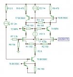
Listen further, please. 2SK170 was developed for audio having exceptional sonic quality, linearity, amplifying ability and noise figure, features very hard to combine (as high Gm brings about high capacitances). A well-matched complementary pair is provided too, which is even harder to do. Only Toshiba has managed to accomplish all that. These devices have no equivalents.I feel the U403 is perfectly used here
It is not about the differential VAS. The single VAS performs poorly, looks poor, it`s the poor man´s VAS. The hole amplifier should be balanced. But this theory of special frequency compensation to achieve high slew rate does not make sense. It`s rather a special mess. Just think!
Why? Gain should not be a problem with high load impedances, you could even apply GNF.Would question the concept
Attachments
Hi Lumba,
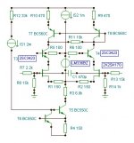
why a med power device for the cascode?
What voltage is the lm336?
Why is the source resistor (R2) set to 2k2 when the NFB resistor (R14) is 1k0?
What does R11 (10k) achieve?
why a med power device for the cascode?
What voltage is the lm336?
Why is the source resistor (R2) set to 2k2 when the NFB resistor (R14) is 1k0?
What does R11 (10k) achieve?
Lumba, I can't argue that the 2SK170 isn't a nice part 😀
However, I really don't want to introduce global negative feedback in an amp that features a feedback-less output stage. And I'm sure that we agree 100% here!
By the way I have some U402 lying around here - once more thank you very much Marcel! - it would be a nice opportunity to bring them to good use.
Have fun, Hannes
Hi Andrew,
we are discussing possible solutions, the values are probably not final, R8/R13 set the input impedances, R11 the gain. R7/R14 are not important for balance but may be equal. LM336BZ-5V would be fine here. T3/T4 dissipate around 50mW, smaller types can be chosen.
we are discussing possible solutions, the values are probably not final, R8/R13 set the input impedances, R11 the gain. R7/R14 are not important for balance but may be equal. LM336BZ-5V would be fine here. T3/T4 dissipate around 50mW, smaller types can be chosen.
Hannes,
I wrote a small early morning transhumanistic palindrome...goes like this... cough...:
You are searching for the truth
It is written in the stars
But may appear one bright sunny day
When you spot it
Please
Let me know
Very soon
!
😀
I wrote a small early morning transhumanistic palindrome...goes like this... cough...:
You are searching for the truth
It is written in the stars
But may appear one bright sunny day
When you spot it
Please
Let me know
Very soon
!
😀
- Status
- Not open for further replies.
- Home
- Amplifiers
- Solid State
- Effect on freq. compensation by substituting transistors?