Just do it like it is , probably the transistor 100K resistor must be 10K or so , but the concept should work .
If you don't have any plate voltage (and you really don't), you won't have a lot of gain. I would suggest to use the values shown in the data sheet. Choose your gain based on the step-up ratio of the mic transformer and the output specs of the microphone. Shoot for 1-2V output.
I am talking the LND150 buffered circuit on post #15 and explaining why not even that is enough.I appreciate the input but I'm a little confused. I don't have a 100k resistor to ground in my current setup, that's the suggestion for the LND150 follower circuit. MY current circuit is the hand drawn circuit several posts previous to that one.
As far as the pentode gain goes. All the really high gain amps that use ef86 have big plate resistors while wrenchone is saying I should follow he numbers in the datasheet..which I was wondering too. Sadly JMFahey, I can't quite follow your suggestions due to my limited electronics knowledge. I was told the high voltage LND150 would work well as a follower after the pentode to buffer the impedance. The circuit withe the LND150 and the 100K resistor added was a suggestion
Of course, not using a buffer is even worse, much worse.
I suggested 2 ways to still get the "pentode sound" you are after but at a more sensible level and able to drive the loads you mention.
To boot they are simple and inexpensive.
On a phone now, notebook crashed, at the moment not able to draw a schematic, but it' not much more complex than those already here.
JM-
You could always just hand-draw a schematic and take a pic with your phone - I am curious as to what you'd suggest in this case.
You could always just hand-draw a schematic and take a pic with your phone - I am curious as to what you'd suggest in this case.
Humourously my schematic drawing program disappeared so that's exactly what I did result in my child's schematic above.
JMFAhey I too would be very interested as to what you'd suggest/draw.
JMFAhey I too would be very interested as to what you'd suggest/draw.
WHile I'm hopefully awaiting JMFaney's schematic offerings(and I say that earnestly), and the LND150s I ordered anyway. I thought I'd goof around and throw one of the shure M68 input transformers on the output. Definitely get a boost in gain , about 12-15db and a fatter/bigger sound but a little less top end, some attenuation of the higher frequencies. Still sounds good , just not as crisp as no transformer. I make them the same volume by eye using the wave forms to have a good listen to the sound.
Could be the sound of the mismatch with a little transformer thrown in.
Could be the sound of the mismatch with a little transformer thrown in.
Last edited:
I guess he did. Well I implemented the LND150 follower as per the schematic I posted (though I put the .22 cap between the EF86 plate and the gate of the LND150. Worked very well. Piles of gain now. I'd reccommend it.
Here's my last question. The 10uf electrolytic cap on the ouput, what sort of voltage should I use? Just be sure for my testing I used a high voltage(450V) cap but it seems to me this might be like cathode bypass cap and could probably be more like 25 or 50 volts. yes? no?
Here's my last question. The 10uf electrolytic cap on the ouput, what sort of voltage should I use? Just be sure for my testing I used a high voltage(450V) cap but it seems to me this might be like cathode bypass cap and could probably be more like 25 or 50 volts. yes? no?
l
What .22 cap? How do you bias the gate now?
With DC coupling from the valve to the source follower, you would have almost the complete supply voltage across the output capacitor until the valve heats up.
per the schematic I posted (though I put the .22 cap between the EF86 plate and the gate of the LND150
What .22 cap? How do you bias the gate now?
With DC coupling from the valve to the source follower, you would have almost the complete supply voltage across the output capacitor until the valve heats up.
On my original schematic (without the follower) I had a .22 cap on the output of the EF86 circuit.
The fellow that suggested the LND150 follower and added it on to my schematic took the .22cap out. (post 15 I think) I put it back in my implementation (It was already in the pre on the plate of the EF86, I just hooked it to the diodes and the Gate. Seems to work fine. Is it unnecessary? Problematic?
The fellow that suggested the LND150 follower and added it on to my schematic took the .22cap out. (post 15 I think) I put it back in my implementation (It was already in the pre on the plate of the EF86, I just hooked it to the diodes and the Gate. Seems to work fine. Is it unnecessary? Problematic?
It sounds like the bias voltage of the gate of the output MOSFET is undefined, which could lead to all sorts of unpredictable behaviour (like an amplifier that works fine at first, but slowly fades out when you keep it turned on too long, except on a wet day).
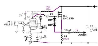
Yes. I would remove the 0.22 uF capacitor, use a 450 V-rated output capacitor and add some protection (like Zeners in antiseries) across the output to ensure you don't blow up whatever or shock whoever is connected to the output during power-on or when the amplifier is driven into clipping.
Thanks. The 10uf output cap is 450V.
Putting a meter across the output does show 126V briefly befor eth preamp warms up. Hqppily this didn't blow my UAD Appollo Twin as I was testing it.
Also happily diodes are cheap.
Putting a meter across the output does show 126V briefly befor eth preamp warms up. Hqppily this didn't blow my UAD Appollo Twin as I was testing it.
Also happily diodes are cheap.
On the LND150 drain? 167V
Sorry made a misreading, more like 40+ V on the output at power up, goes down very quickly so hard to read
which is very similar to the 45V that the ef86 plate has
Sorry made a misreading, more like 40+ V on the output at power up, goes down very quickly so hard to read
which is very similar to the 45V that the ef86 plate has
Last edited:
What is the B+ supply voltage at the last filter cap of the power supply before it goes to the tube circuit and source follower?
45V on the EF86 is less than half what you need for good operation. I would shoot for a minimum of 100V.
You need at least 200V B+, 300 would be even better for low distortion and good drive ability.
As alluded to earlier, the 1M resistor to the screen of the tube is too high a value as well. It lowers GM, Rp, and gain. 330K to 470K is better as it promotes an operating point with higher GM and more linearity.
171 V.
The voltage of the EF86 has gone down a little with the addition of the source follower but it was only about 53V before. That part of the circuit is stock Akai/Roberts. I did try changing the plate, cathode and screen resistor as suggested and as dictated by the datasheet. I think I did 100k 370k and 1k and while there was a slight increase in voltage certainly there wasn't a significant increase in gain. I might try lowering the screen resistor to closer to 680k as that's what the datasheet seems to suggest with a 220k plate and a 2.2k cathode resistor. The LND150 follower gives me a goodly amount of gain
The voltage of the EF86 has gone down a little with the addition of the source follower but it was only about 53V before. That part of the circuit is stock Akai/Roberts. I did try changing the plate, cathode and screen resistor as suggested and as dictated by the datasheet. I think I did 100k 370k and 1k and while there was a slight increase in voltage certainly there wasn't a significant increase in gain. I might try lowering the screen resistor to closer to 680k as that's what the datasheet seems to suggest with a 220k plate and a 2.2k cathode resistor. The LND150 follower gives me a goodly amount of gain
- Home
- Amplifiers
- Tubes / Valves
- EF86 Microphone preamp with solid state follower