Ok so I am trying out some tube mikes with an ef800
Something like the AMI circuits UM47 Alt Tube Schematics
Now I also simulated this circuit and kathode current is around 0.7mA and plate voltage is around 14v....
Seems a little bit low to me but it does work.
Now even more strange. I accidently wired the kathode to gnd so there was no bias (zero grid voltage) but it just worked.
So I tried to do this in ltspice and indeed it keeps working.
Kathode current is 0.72mA (almost the same) and anode voltage changed to around 12v.
Maximum output and distortion was almost the same.
In real life the filament is only at 5.6v so kathode current will be lower and anode voltage will be a little higher.
The original U47 with the vf14 gave an anode voltage of around 35v.
So if we could leave out those 2 resistors, there is less components and if the filament supply has ripple it wouldn't get to the signal.
Would it harm the tube operating it this way?
Also why would we operate at such low anode voltage? (tube life? less noise? less heat?)
And it really sounds great using it this way....
> no bias (zero grid voltage) but it just worked.
Grid input impedance drops from >>100Megs for negative grid to 1k for slightly positive grid. At zero grid the impedance is a few K, unpredictable.
A SPICE signal will drive this (or anything).
A condenser mike head loses bass (and gains hiss) for any thing less than a dozen MEGs.
Archut knew what he was doing.
Well that was also what I was thinking but in reality it still has bass....
I think because of the high value grid leak resistor, connecting the kathode to GND this is more like grid leak bias and because of the small signals it works.
Grid leak bias is impossible to simulate I think.
Actually I tried simulating with a high output impedance signal generator to check for problems because of the low grid impedance at 0V.
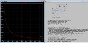
Try this model see you can see grid leak bias voltage and input impedance measured when cathode resistor is zero.
Code:
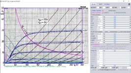
**** EF80 ****************************************** * Created on 01/02/2021 19:38 using paint_kip.jar
* [URL="http://www.dmitrynizh.com/tubeparams_image.htm"]www.dmitrynizh.com/tubeparams_image.htm[/URL]
* Plate Curves image file: ef80.png
* Data source link: <plate curves URL>
*----------------------------------------------------------------------------------
.SUBCKT EF80 P G2 G K ; LTSpice tetrode.asy pinout
* .SUBCKT EF80 P G K G2 ; Koren Pentode Pspice pinout
+ PARAMS: MU=50 KG1=461.8 KP=282.74 KVB=404.93 VCT=0 EX=1.225 KG2=592.55 KNEE=944.64 KVC=1.68
+   KD=0.2916 KC=0.3724 KR1=8.45E-4 KR2=0.08448 KVBG=0.00585 KB1=1.84 KB2=2 KB3=2 KB4=0.96 KVBGI=0.01888 KNK=0 KNG=0
+ CCG=7.5P CGP=3.3P CCP=0.012P VGOFF=-0.6 IGA=3E-10 IGB=0.02556 IGC=20 IGEX=1.413
* Vp_MAX=350 Ip_MAX=50 Vg_step=1 Vg_start=1 Vg_count=8
* X_MIN=42 Y_MIN=54 X_SIZE=763 Y_SIZE=547 FSZ_X=1296 FSZ_Y=736 XYGrid=false
* Rp=1600 Vg_ac=23.5 P_max=2.5 Vg_qui=-23.4 Vp_qui=240
* showLoadLine=n showIp=y isDHP=n isPP=n isAsymPP=n isUL=n showDissipLimit=y
* showIg1=y isInputSnapped=n addLocalNFB=n
* XYProjections=n harmonicPlot=y dissipPlot=n
* UL=0.43 EG2=170 gridLevel2=y addKink=n isTanhKnee=n advSigmoid=y
*----------------------------------------------------------------------------------
RE1  7 0  1G    ; DUMMY SO NODE 7 HAS 2 CONNECTIONS
E1   7 0  VALUE=  ; E1 BREAKS UP LONG EQUATION FOR G1.
+{V(G2,K)/KP*LOG(1+EXP((1/MU+(VCT+V(G,K))/SQRT(KVB+V(G2,K)*V(G2,K)))*KP))}
RE2  6 0  1G    ; DUMMY SO NODE 6 HAS 2 CONNECTIONS
E2  6 0  VALUE={(PWR(V(7),EX)+PWRS(V(7),EX))} ; Kg1 times KIT current
E4   8 0  VALUE={V(P,K)/KNEE/(KVBGI+V(6)*KVBG)}
E5  81 0  VALUE={PWR(V(8),KB1)}
E6  82 0  VALUE={PWR(V(8),KB2)}
E7  83 0  VALUE={PWR(V(8),KB3)}
E8   9 0  VALUE={PWR(1-EXP(-V(81)*(KC+KR1*V(82))/(KD+KR2*V(83))),KB4)*1.5708}
RE4  8 0  1
RE5 81 0  1
RE6 82 0  1
RE7 83 0  1
RE8  9 0  1
G1   P K  VALUE={V(6)/KG1*V(9)}
G2   G2 K  VALUE={V(6)/KG2*(KVC-V(9))}
RCP  P K  1G     ; FOR CONVERGENCE
C1   K G  {CCG}  ; CATHODE-GRID 1
C2   G P  {CGP}  ; GRID 1-PLATE
C3   K P  {CCP}  ; CATHODE-PLATE
RE23 G 0 1G
GG G K VALUE={(IGA+IGB/(IGC+V(P,K)))*(MU/KG1)*
+(PWR(V(G,K)-VGOFF,IGEX)+PWRS(V(G,K)-VGOFF,IGEX))}
.ENDS
Attachments
Thanks for the model.
I also did some measurements.
The Kathode current in the microphone is 750µA.
I also tried to measure the grid voltage but using a voltmeter with 10Mohm this is rather difficult.
I used 1Gohm in series with the voltmeter and then multiplied by the division 1010Mohm/10Mohm.
I measured 12mV so that calculates to around 1.2V at the grid.
I have read some things about using 1Gohm as the grid leak. It is rather high but people seem to like it.
Couldn't it be that using it this way the valve will operate more like grid leak bias then is presumed in the original circuit.
In my case I have Hum when using the original circuit. Problem is in the filament supply I think altough it is stabilized using a voltage regulator and a lot of capacitance.
when the kathode is connected to ground the filament supply doesn't add to the signal and the MIC is very quite.
Otherwise I have hum and a little bit more noise.
Also when connecting the kathode to GND I have more gain and a little bit more highs.
I'm really curious about this circuit.
I don't think the input impedance is going down very fast when you ground the cathode as shown in the attachment. Not to worry about it, as it works normally. When Rk=0, the grid leak bias still exist at about same level so is the input Z I think. The output level maybe affected however.
Attachments
Last edited:
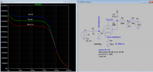
Can you confirm? I plug in 1.2V for VGOFF, cathode current gone down, I plug in 0.12V, cathode current is 754uA which is same as you measured. So is it 0.12V or 1.2V?I also did some measurements.
The Kathode current in the microphone is 750µA.
I also tried to measure the grid voltage but using a voltmeter with 10Mohm this is rather difficult.
I used 1Gohm in series with the voltmeter and then multiplied by the division 1010Mohm/10Mohm.
I measured 12mV so that calculates to around 1.2V at the grid.
I havent weighed in, because I'm still a noob myself,
But I would assume to former, 0.12V and a mistake with 0's....I do this often!
I am often wrong, and my opinion differs from others, Like PRR.
In this case, I tend to agree with him.
In my small foray into learning about doing the very same, building a valve condenser mic, thanks to a mammoth thread here and GroupDIY - I would advise that some negative bias will be preferable, in the end.
I have run russian submini valves at 0 bias, or very close to it, less than a Si diode drop, and I have found with a signal generator I can obtain gain better than I imagined. Even so, looking at the data sheet curves again, for the valve I used, 6S6B, and it can be seen the curves look good at a low bias voltage, and into positive territory. But, it says nothing of the grid Z.
I suspect that the ability of the source to drive the grid determines all here.
Why not:
Connect a 250k pot as rheostat, in series with the input signal.
Set to minimum R, inject signal, measure gain.
Then increase input rheostat until the gain/output is halved.
Then measure the R of the rheostat.
Then you'll have an idea of what impedance you are trying to drive, as far as the signal is concerned. The 1000M grid leak becomes clearer.
I think/hope my reckoning is 100% correct on the above, but welcome any correction to my reasoning
Last edited:
OP just measured the grid is 0.12V (or 1.2V) when he grounded the cathode.At zero grid the impedance is a few K, unpredictable.
It's very difficult to exactly measure this. Can try again.Can you confirm? I plug in 1.2V for VGOFF, cathode current gone down, I plug in 0.12V, cathode current is 754uA which is same as you measured. So is it 0.12V or 1.2V?
Also the supply I used gives a little bit more voltage (around 150-160v)
I have a little bit more then 50v on the anode.
Then something different abou tthe heater supply. Does anybody now if the standard lm78xx still gives some hum?
Looks pretty good on the scope but measuring less then a few mV is difficult. This supply is normally connected at the kathode using some resistor divider but this gives me hum
Would an lm317 be better? I know they are a lot better for noise.
Yup.
I find 0.12V when Rk = 0 more plausible.
I.e. the 6S6B biased up about 0.25 - 0.4V with Rk at 0R.
Sure this is already a triode, but just could do a mediocre job - a better match in many areas would help
Not my site, nor any Affiliation but this sums up my feeling from some brief experiments of my own.
Phaedrus Audio Home › 5840_n...
CK5840 page - Phaedrus Audio
It's very difficult to exactly measure this. Can try again.
Also the supply I used gives a little bit more voltage (around 150-160v)
I have a little bit more then 50v on the anode.
Then something different abou tthe heater supply. Does anybody now if the standard lm78xx still gives some hum?
Looks pretty good on the scope but measuring less then a few mV is difficult. This supply is normally connected at the kathode using some resistor divider but this gives me hum
Would an lm317 be better? I know they are a lot better for noise.
My sim result is closer now to above difference. For VGOFF 1.2V, I get cathode 710uA, anode 58V and supply 150V. So I am happy with 1.2V grid? 🙂
For hum, maybe a hum pot can help to cancel it out.
Last edited:
Grid leak bias is the way to go in this kind of circuit. The only problem with it is unpredictability. Different tubes of the same type may have different negative g1 voltages under same circuit conditions, and it also depends on the value of grid leak resistor. Btw, g1 voltage can be deduced from plate voltage and cathode current if volt-ampere characteristic of a given tube is known.
The important caveat for practical use of grid leak is that input signal should be well within bias voltage, otherwise there will be distortion due to g1 conductance.
The important caveat for practical use of grid leak is that input signal should be well within bias voltage, otherwise there will be distortion due to g1 conductance.
So far the experience has been that the grid leak method works quite good.
-More Gain
-Less Noise
-More hi-end response
-No Hum (has to do with my heater supply)
I wonder why they didn't used this method in the first place.... less heat and less components...
The voltage coming from the cell is only a few mV.
-More Gain
-Less Noise
-More hi-end response
-No Hum (has to do with my heater supply)
I wonder why they didn't used this method in the first place.... less heat and less components...
The voltage coming from the cell is only a few mV.
- Home
- Amplifiers
- Tubes / Valves
- ef800 low current triode strapped