Hi there,
I am currently fighting with my Spice in order to create a good CCS based on the EF184 / 6EJ7 pentode. Anode current should be 8.5mA, I have about 170V available for the CCS.
As this is my first attempt on CCS design, a few questions came up:
1. The easiest way to operate a pentode as CCS seems to be connecting G1 to ground and using the cathode resistor to set the desired total current (I_A+I_G2). This works, but leads to a relatively small R_k of about 200 Ohms.
2. In Spice simulations, the CCS behaved much better with higher values of R_k in the 2kOhms region, but in order to get the desired current, I have to pull the grid up a few volts via a voltage divider from the B+ then. I have seen this in different circuits, but I am not sure which approach is the better.
Which is the correct way to go here?
3. Next question is about the G2 resistor: The EF184 datasheet says 0Ohms for U_A=170V, U_G2=170V. Only for higher voltages a G2 resistor of up to 12kOhms @ 230V is mentioned. Are there design rules that let me calculate the correct value for the G2 resistor?
4. For the SPICE experts: The EF184 model I have seems to mess up G2 current, which is only a few hundred µA when the datasheet says there should be 4mA. Does anyone have a EF184/6EJ7 model giving better values for G2 current?
Thanks for your help!
Andreas
Hi there,
I am currently fighting with my Spice in order to create a good CCS based on the EF184 / 6EJ7 pentode. Anode current should be 8.5mA, I have about 170V available for the CCS.
You can get a "white paper" about this very thing by entering (no quotes) "a current source for vacuum tubes + G. R. Kaelin + C. R. Viswanathen" in the Google search window. That should take you to a source for downloading the *.pdf.
Then you can fuggedaboud Spice and design it the old fashioned way: with a scientific calculator. That way, no worries about invalid and/or impractical Spice models.
"Oldfashioned way" isn´t by using scientific calculator. It is by using slide-ruler, but that was maybe before your time😉.
Andreas,
My model behaves better. PM or E-mail me with your E-mail address.
Andreas,
My model behaves better. PM or E-mail me with your E-mail address.
Hi there,
thanks for the model - works great!
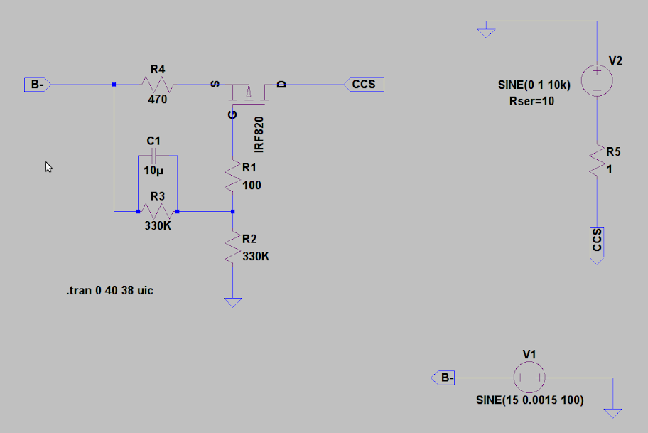
I simulated the following EF184 current sink in Spice, on the right side is the original FET sink it is going to replace.
A short performance check yielded the following results (programmed current is 9.4mA):
Excitation ......... current change EF184 ........ current change original
none ................ 0.09µA ............................ 0.02µA
10Hz, 1V pp ...... 0.66µA ........................... 20µA
20Hz ............... 0.5µA .............................. 20µA
1kHz ............... 0.5µA .............................. 20µA
10kHz .............. 0.5µA ............................. 24µA
20kHz .............. 0.5µA ............................. 33µA
30kHz .............. 0.52µA ........................... 44µA
Frequency response of the two circuits looks like this:
 vs.
vs.

Please comment on the following topics:
a) design (errors) of my EF184 sink
b) comparison of performance, LF(HF) roll-off
Comments are very, very welcome! Otherwise I have to warn you that I will heat the iron and test this thing^^
Greetings,
Andreas
thanks for the model - works great!
I simulated the following EF184 current sink in Spice, on the right side is the original FET sink it is going to replace.
An externally hosted image should be here but it was not working when we last tested it.
A short performance check yielded the following results (programmed current is 9.4mA):
Excitation ......... current change EF184 ........ current change original
none ................ 0.09µA ............................ 0.02µA
10Hz, 1V pp ...... 0.66µA ........................... 20µA
20Hz ............... 0.5µA .............................. 20µA
1kHz ............... 0.5µA .............................. 20µA
10kHz .............. 0.5µA ............................. 24µA
20kHz .............. 0.5µA ............................. 33µA
30kHz .............. 0.52µA ........................... 44µA
Frequency response of the two circuits looks like this:
Please comment on the following topics:
a) design (errors) of my EF184 sink
b) comparison of performance, LF(HF) roll-off
Comments are very, very welcome! Otherwise I have to warn you that I will heat the iron and test this thing^^
Greetings,
Andreas
Last edited:
R5 seems suspiciously small. And likewise, C1 is suspiciously large.
Be careful about cathode to heater ratings!
Be careful about cathode to heater ratings!
R5 seems suspiciously small. And likewise, C1 is suspiciously large.
Be careful about cathode to heater ratings!
Thanks SY,
good points to consider. Easiest one first: The EF184 has a separate heater winding tied to B-, so V_hk will not be a problem.
R5 and C1 ... You found the two parts I was most doubtful about in this circuit.
I have often seen much higher values for R5, but with the roughly 3mA G2 current, screen voltage will drop very low if I feed the screens as shown. And currently I do not plan for a separate (higher) screen supply.
What do you think is more acceptable: Low value screen resistor or very low screen voltage?
C1 ... I played around a bit with this one, and smaller values moved the LF roll-off into the audio band - I did not expect high C1 values to be problematic.
What problems do I possibly introduce by making C1 that high?
Thanks and greetings,
Andreas
C1 and R5 form a high pass filter, ensuring that g2 follows the cathode voltage for AC purposes. Below the rolloff the CCS impedance will fall (because the valve is beginning to work more like a triode), and around the rolloff the impedance may become reactive.
My guess is that a larger R5 will not do much harm. It may reduce partition noise by reducing the proportion of cathode current which goes to g2, but your noise may be dominated by the potential divider setting g1 voltage. On the other hand, it may make the output impedance more (or less - not sure) non-linear.
I ought to say that I have no experience of using CCS myself, so my thoughts are purely theoretical.
Why not tie the screen resistor to B+ so it can be a much higher value? That will also allow the cap to be made quite a bit smaller.
edit: Since increasing the cathode resistor increases the source impedance, you can also gain an improvement by making it larger, then adjusting the voltage divider to the control grid to get the correct operating current. Note though, if this CCS is in a cathode circuit, you hit the diminishing returns limit fairly quickly.
edit: Since increasing the cathode resistor increases the source impedance, you can also gain an improvement by making it larger, then adjusting the voltage divider to the control grid to get the correct operating current. Note though, if this CCS is in a cathode circuit, you hit the diminishing returns limit fairly quickly.
Why not tie the screen resistor to B+ so it can be a much higher value? That will also allow the cap to be made quite a bit smaller.
In principle, that sounds like a good idea. However, the following questions come to my mind:
To ensure safe operation and failure modes of the complete amplifier, the B- supply will only start after left and right channel B+ is there. So there would be a certain time during startup when the EF184 has only its heater powered and about 400V on the screens - not sure if this is acceptable...?
edit: Since increasing the cathode resistor increases the source impedance, you can also gain an improvement by making it larger, then adjusting the voltage divider to the control grid to get the correct operating current. Note though, if this CCS is in a cathode circuit, you hit the diminishing returns limit fairly quickly.
This is what I already did to a certain extent. Most ccs designs tie the grid to ground and use a small cathode resistor.
I am not quite sure what limit you mean, but it sounds if this could be important - would you mind explaining your thought in more detail?
jacruby: could you post your ef84 spice model please?
I obtained the better model from revintage, see this thread further above. Just PM him - as I do not know if it is ok to post his model here.
Thanks and greetings,
Andreas
Hi guys,
I'm new here and I'm sorry for ressurecting an old topic like this, but I need some help.
I'm trying to simulate a Morgan Jones tone control which appears in the Valve Amplifiers 4th edition.
So, I need a EF184 spice model, can anybody help me ?
Thanks a lot.
Carlos Pedrini
I'm new here and I'm sorry for ressurecting an old topic like this, but I need some help.
I'm trying to simulate a Morgan Jones tone control which appears in the Valve Amplifiers 4th edition.
So, I need a EF184 spice model, can anybody help me ?
Thanks a lot.
Carlos Pedrini
- Status
- Not open for further replies.
- Home
- Amplifiers
- Tubes / Valves
- EF184 as ccs / design questions / spice model