Hey guys.
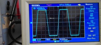
I've been having trouble 'getting right' the VAS-EF stage setting. I've been having problems with a 'glitch', oscillation on the negative side of the waveform that I'm not able to fix.
Can anyone give me a light on what might be going on?
It is a small oscillation that only appears when mowing the wave and only on the negative side.
Please see this presentation - specifically slide 5 - for some helpful hints
rail sticking and glitch
rail sticking and glitch
Thank's Bonsai. I will read carefully and try to apply for testing.Please see this presentation - specifically slide 5 - for some helpful hints
rail sticking and glitch
I'm currently using 39pF.There is usually a capacitor on VAS transistor 47-100pf ?
Look carefully at the diode across the base to emitter of the VAS transistor. You must use a fast (switch in 10-20 ns) low capacitance diode. A good choice is a BAS21J - it’s SMD unfortunately but there are leaded equivalents.
I will test and report soon. Thank you for the tipsLook carefully at the diode across the base to emitter of the VAS transistor. You must use a fast (switch in 10-20 ns) low capacitance diode. A good choice is a BAS21J - it’s SMD unfortunately but there are leaded equivalents.
The VAS transistor is being heavily over-driven and saturating during the clipping period - with no current limiting other than the 10 ohm emitter resistor it will be pulling perhaps 100mA or more. When clipping ends the VAS transistor takes a while to recover from the saturation, taking several microseconds typically, by which time the feedback network is completely out of lock and the spikey transient you see is the feedback loop recoveringCan anyone give me a light on what might be going on?
control.
If you can limit the VAS current to about twice its nominal working current this will greatly reduce this effect while still allowing full current swing at the VAS output. This also protects the VAS from over-dissipation should the positive-side output device(s)/drivers(s) fail shorted to the +ve rail, which is a handy extra bonus.
The typical limiting circuit uses the voltage across the VAS emitter resistor to sense the current and provide a Vbe drop to turn on a limited transistor that pulls the VAS input towards the rail.
The VAS transistor is being heavily over-driven and saturating during the clipping period - with no current limiting other than the 10 ohm emitter resistor it will be pulling perhaps 100mA or more. When clipping ends the VAS transistor takes a while to recover from the saturation, taking several microseconds typically, by which time the feedback network is completely out of lock and the spikey transient you see is the feedback loop recovering
control.
If you can limit the VAS current to about twice its nominal working current this will greatly reduce this effect while still allowing full current swing at the VAS output. This also protects the VAS from over-dissipation should the positive-side output device(s)/drivers(s) fail shorted to the +ve rail, which is a handy extra bonus.
The typical limiting circuit uses the voltage across the VAS emitter resistor to sense the current and provide a Vbe drop to turn on a limited transistor that pulls the VAS input towards the rail.
Thank you Mark. There is really an overload in the VAS as I could see in practice. I'll arrange circuit fixes. Thanks for the feedback 🙂
Hey BonsaiPlease see this presentation - specifically slide 5 - for some helpful hints
rail sticking and glitch
I tested the solution provided in the file you shared and I was successful. Thank you again. Your name can be found in the amplifier's technical manual. Thanks.
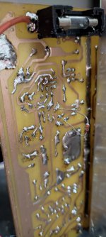
Attachments
- Home
- Amplifiers
- Solid State
- EF-VAS 'glitch' problem