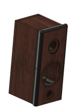
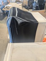
To spice up my boring 2 way build I am going to try some 3d printed edge diffraction pieces to see what difference they might make.
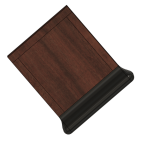
I will be starting with this aerofoil/teardrop shape. This is a pretty small one but I can make it wayyyyy bigger which is probably what I will try next.
Does anyone else have a shape they would like me to test? Let me know. Let's do some science!
I will be starting with this aerofoil/teardrop shape. This is a pretty small one but I can make it wayyyyy bigger which is probably what I will try next.
Does anyone else have a shape they would like me to test? Let me know. Let's do some science!
Attachments

Hornresp has a 2d pixel based editor as one of its features, which lets you experiment with various baffle profiles and see what it does to the coherence of the sound waves as they expand out from the cone.
One 'ideal' is probably on a continuum between a heart-like shape and an aerofoil, depending on how much horn loading you want. But I'm talking about a continuous curve with no 'bumps' if you run a finger from the edge of the tweeter dome, along its wave-guide, and all the way out to the back of the box.
One 'ideal' is probably on a continuum between a heart-like shape and an aerofoil, depending on how much horn loading you want. But I'm talking about a continuous curve with no 'bumps' if you run a finger from the edge of the tweeter dome, along its wave-guide, and all the way out to the back of the box.
Abstract,
I believe that can be done. Its a bit harder to model but I can figure it out.
Is the tweeter then the driver that is most affected by diffraction? I thought the mids were also affected significantly
I believe that can be done. Its a bit harder to model but I can figure it out.
Is the tweeter then the driver that is most affected by diffraction? I thought the mids were also affected significantly
Lol. Fusion 360 is pretty easy. Its really good for picking it up quickly and getting basic engineering stuff modeled. It falls short in the more organic design department.
Fusion is free for personal use if you want to try your hand at it. There is course on Youtube called "learn Fusion 360 in 30 days". I knocked that out in about 2 weeks but that is exactly where I got my start from. Give it a try. If I can figure it out, so can you.
Fusion is free for personal use if you want to try your hand at it. There is course on Youtube called "learn Fusion 360 in 30 days". I knocked that out in about 2 weeks but that is exactly where I got my start from. Give it a try. If I can figure it out, so can you.
I would start with half round or quarter round, I guess eventually you end up with a sphere, then an egg. If you are going to shape the sides and back, then go gradually to a tear drop shaped enclosure. Where it gets interesting is the transition between drivers. Also, it would be interesting to see the difference between a tweeter waveguide turned into a drop shape (Abstract’s idea) and with a highly streamlined no edge tear drop shape like the Nautilus.
Yes, midrange is affected down to 250-500hz approximately, where the room takes over and the enclosure becomes relatively small. For example no one puts edge treatment on a subwoofer, the waves are so huge and the box is relatively very tiny.
There are horns where the trailing edge curls back on itself. Kind of like a fractal or organic curve. Maybe you could print an edge like that? It would be big though, lots of material.
Last edited:
You should have a look at OpenSCAD as it is entirely code based. You call functions to make a drawing. I keep planning to learn something else but I keep going back to OpenSCAD.You're still way ahead of me when comes to 3d CAD layout. Whenever I attempt to decipher the UI of some CAD program, I end up wondering maybe I could just write code for it as an easier option?
start with half round or quarter round
A study was published in SpeakerBuiider (or what followed) showed that a significant quarter-round i needed to affect anything but the extreme top end.(IIRC up to 4” radius was tested).
dave
Baffle edge diffraction is red herring…..if a baffle exists, regardless of its edge treatment, there will be diffraction. The issue isn’t or shouldn’t be how it effects the frequency response but instead how it effects directivity and power response. Best case scenario is always going to be no baffle at all……..impractical for most. The effective compromise will be the smallest baffle possible.
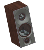
Well we are going to test all of this. I will test the off axis response to see how that is affected.
I will try a half round.
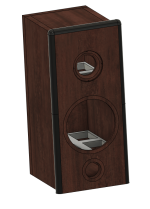
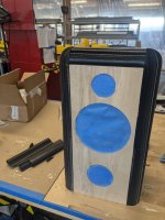
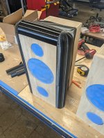
This is the large tear drop I will be testing
I will try a half round.
This is the large tear drop I will be testing
Attachments
Interesting. I'll have to find this. ThanksA study was published in SpeakerBuiider (or what followed) showed that a significant quarter-round i needed to affect anything but the extreme top end.(IIRC up to 4” radius was tested).
dave
I have to play with the organic CAD tools to do the gradual shape thing. Making that gradual shape is a goofy sort of CAD work flow. I did it by accident the other day making something unrelated and thought "man, this would be perfect for a tweeter. I should remember how I did this" and, of course, have already forgotten how I did that.I would start with half round or quarter round, I guess eventually you end up with a sphere, then an egg. If you are going to shape the sides and back, then go gradually to a tear drop shaped enclosure. Where it gets interesting is the transition between drivers. Also, it would be interesting to see the difference between a tweeter waveguide turned into a drop shape (Abstract’s idea) and with a highly streamlined no edge tear drop shape like the Nautilus.
Yes, midrange is affected down to 250-500hz approximately, where the room takes over and the enclosure becomes relatively small. For example no one puts edge treatment on a subwoofer, the waves are so huge and the box is relatively very tiny.
There are horns where the trailing edge curls back on itself. Kind of like a fractal or organic curve. Maybe you could print an edge like that? It would be big though, lots of material.
I have the paid version of Fusion 360 at work. That will be gone in a year and I need to start using SolidWorks since thats what all my customers use. I set out learning CAD just to make aero stuff for my track car and now its a major part of my job at work. Funny how that happens.You should have a look at OpenSCAD as it is entirely code based. You call functions to make a drawing. I keep planning to learn something else but I keep going back to OpenSCAD.
I remember that, a large radius is required. I messed around with 8” concrete form tubes and stuck them to my speakers. It made a difference in midrange and up, but they kept falling off. 🤣A study was published in SpeakerBuiider (or what followed) showed that a significant quarter-round i needed to affect anything but the extreme top end.(IIRC up to 4” radius was tested).
dave
I also messed with wool felt on the edges. It required large amounts of material. I used 4” wide strips 3/4” thick and layered them up in a straight line and in a curve. There was a very different effect than the tubes, more direct sound, less room interaction. It definitely cleaned up the vocals and the imaging. Wife didn’t like it. 🫤
Engineering is where you do the calculations to predict the result and then run the experiment to verify the calculations, documenting both along the way. That's the way to make forward progress. Guessing, building and testing is fun but can be much more time consuming and expensive.
I think you would enjoy learning to model baffles in the available free software. Visaton's boxsim is excellent but some what limited in the geometry you can create but produces every test plot you could want in a single click. You can open the example project and then simply change the shape and size of the box / baffle as well as move drivers around on the baffle and test things in just a few minutes. The example is a two way speaker. You will find that perfectly centered or symmetric locations for the drivers will quadruple or double respectively the baffle effects you see at any given frequency. Move the driver to 1/3 of the baffle width from an edge and see the effect reduced on the upper frequencies. Make the baffle wide, say 50 cm meters or more with the drivers offset from the center and the edges rounded and see the baffle effects reduced to around 1 dB.
To model more complex baffles the baffle modeling tool in VituixCAD is good. It works on one driver at a time, but allows for more arbitrary baffle shapes. I was able to model the Linkwitz speakers with VituixCAD.
Here's an example from boxsim where I have 3" dome midranges on the front and rear of a wide thin cabinet with beveled edges. The drivers are offset from the center the optimal amount to cancel some of the baffle edge effects.


Predicted frequency response. Blue: front driver only Red: rear driver only Black: combine response. Curve with rolled off high frequencies is the power response.

Here is the horizontal directivity graph showing an omni-directional response up to about 2 kHz.
I think you would enjoy learning to model baffles in the available free software. Visaton's boxsim is excellent but some what limited in the geometry you can create but produces every test plot you could want in a single click. You can open the example project and then simply change the shape and size of the box / baffle as well as move drivers around on the baffle and test things in just a few minutes. The example is a two way speaker. You will find that perfectly centered or symmetric locations for the drivers will quadruple or double respectively the baffle effects you see at any given frequency. Move the driver to 1/3 of the baffle width from an edge and see the effect reduced on the upper frequencies. Make the baffle wide, say 50 cm meters or more with the drivers offset from the center and the edges rounded and see the baffle effects reduced to around 1 dB.
To model more complex baffles the baffle modeling tool in VituixCAD is good. It works on one driver at a time, but allows for more arbitrary baffle shapes. I was able to model the Linkwitz speakers with VituixCAD.
Here's an example from boxsim where I have 3" dome midranges on the front and rear of a wide thin cabinet with beveled edges. The drivers are offset from the center the optimal amount to cancel some of the baffle edge effects.
Predicted frequency response. Blue: front driver only Red: rear driver only Black: combine response. Curve with rolled off high frequencies is the power response.
Here is the horizontal directivity graph showing an omni-directional response up to about 2 kHz.
Last edited:
Hi, roundovers need only be as big as fits: if your driver is 1" and its 5" sized baffle/box, use 2" radius and start it right at the tweeter. If you have 2" baffle for the 1" source, 1/2" radius is as big as fits and pretty much as effective. If you have no baffle at all, no radius fits, and thats best you can do and almost the same performance as the previous two. If you have large flat area around a driver, you'd need very big radius roundovers. The baffle supports long wavelength so high radius is needed to mitigate, slap on roundovers and it gets bigger, so interference gets lower in frequency. Although, you could make the baffle approach room dimensions and any edge diffraction related backwave is mixed into all kinds of reflections from room boundaries and objects.
So, either very big structure around a driver, or as small as you can have. The smaller the sttucture isnthe smaller roundovers need to be for very little diffraction related issues in listening window response.
So, either very big structure around a driver, or as small as you can have. The smaller the sttucture isnthe smaller roundovers need to be for very little diffraction related issues in listening window response.
here's one.
a multi-radius round over -- in other words, a parabola -- might deliver aspects of large radius round overs without involving an overly thick front baffle.
if you could model a first approximation -- cut by a commercial large thumbnail router bit -- as well as a comparable mathematical parabola that might be instructive.
I thought about trying that. Grizzly has a hand rail bit that’s really wide, 3 1/8”! It just might work. Now, which way does the curve go?


- Home
- Loudspeakers
- Multi-Way
- Edge Diffraction Testing - Shapes