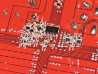
Received this amp which was powering up without REM connected. I found a diode 4148 and NPN marked 24 and PNP marked HR transistors in down the REM path all failed. Replacements chosen using BC846BT/BC856BT. now the amp won't power up and the I cannot get +12vDC to pin 12/13 of the TL494.
All resistors around the area seem to be OK.
Is there a schematic available?
All resistors around the area seem to be OK.
Is there a schematic available?
Looking at the replacements, there may be a problem.
DCV measured directly across base and emitter of the NPN transistor?
DCV directly across D801?
DCV measured directly across base and emitter of the NPN transistor?
DCV directly across D801?
Is the diode open? I think it's being used for under-voltage protection and 13v seems too high.
Is the transistor shorted/leaky.
I think the NPN transistor was supposed to be a digital transistor with internal resistors. Using a transistor without those resistors and no series resistance on the board may be your problem.
Try to get the numbers from the diode before removing it in case it breaks up when desoldering it.
Yes the diode has a marking of A2 on it. A 1N4148 AFAIK
Theres 13vDC on the cathode of D801 fed from the REM terminal. Originally, D801 A2 diode was dead shorted when I started working on this amp.
Curious on if I can use a high ohm rated resistor instead of this diode. REM voltage is not getting to the NPN. Or maybe the diode is backwards? Im not sure.
Theres 13vDC on the cathode of D801 fed from the REM terminal. Originally, D801 A2 diode was dead shorted when I started working on this amp.
Curious on if I can use a high ohm rated resistor instead of this diode. REM voltage is not getting to the NPN. Or maybe the diode is backwards? Im not sure.
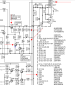
Not great but attached.
Is the original diode open? It's likely something like an 7.5v zener.
Was the NPN transistor shorted or open base to emitter?
Do you have any 'digital' transistors? If not, you could get by by inserting a 1k resistor in series with the gate leg of the standard NPN transistor.
The attached file is very roughly what I think you have. R244 is allowing them to use a standard NPN transistor instead of a digital type transistor.
Attachments
Last edited:
The original diode is shorted end for end. 0 ohms.
You mean put a 1k resistor between the base and emitter? Or do you mean in series with REM?
You mean put a 1k resistor between the base and emitter? Or do you mean in series with REM?
In series in the remote, diode, NPN base. You need something to allow a voltage drop in that circuit. I can't tell if there is a pulldown resistor on that circuit but if you, you can (for testing) insert the resistor at the remote terminal.
I'd use a 7.5v Zener in the place of the diode.
If you're uncertain about the condition of the NPN transistor, replace it.
I'd use a 7.5v Zener in the place of the diode.
If you're uncertain about the condition of the NPN transistor, replace it.
OK the NPN transistor (1B) keeps opening at the base. I guess I need to figure out a solution for the original, which was a (24) transistor?
Is it opening with the Zener and the 1k resistor in the circuit?
The correct part is the right way to do it but this will, at least, get you running and able to test.
The correct part is the right way to do it but this will, at least, get you running and able to test.
No with the resistor and diode inline, the 1B survives but the amp does not power up. Without the resistor, and the 1B transistor fails.
If you used a standard diode, it must be in backwards (reversed polarity).
7.5v are commonly used.
7.5v are commonly used.
I used a 7.5v Zener. With the 1k resistor before the zener the amp does not power up with a good working 1B transistor in place of the '24'
DCV on the following points with the black probe on the emitter of the NPN transistor.
remote terminal
both terminals of the 1k resistor
both terminals of the zener (note striped or other terminal)
base of the NPN transistor
remote terminal
both terminals of the 1k resistor
both terminals of the zener (note striped or other terminal)
base of the NPN transistor
- Home
- General Interest
- Car Audio
- Eclipse PA5422 now won't power up