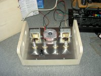
Hello Guys,
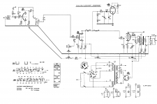
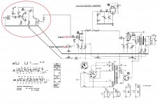
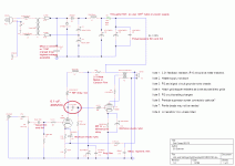
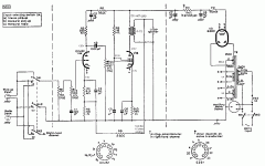
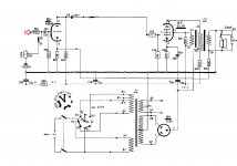
I recently bought 2 pcs. identical "Hornyphon" magnetophones made in Austria with the idea to build with them a stereo tube amplifier. I want to use only the last stage of the amplifier build with the tube ECL82 and the magic eye EM84, but it seems that the schematic is quite complex for me and I can't decide what components to remove. Can you give me some advice, please?

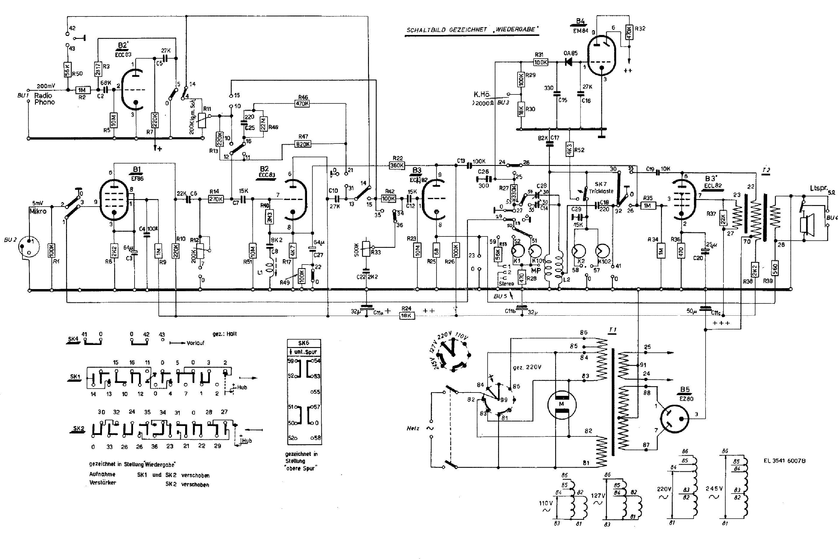
I recently bought 2 pcs. identical "Hornyphon" magnetophones made in Austria with the idea to build with them a stereo tube amplifier. I want to use only the last stage of the amplifier build with the tube ECL82 and the magic eye EM84, but it seems that the schematic is quite complex for me and I can't decide what components to remove. Can you give me some advice, please?


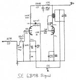
For your audio project (which should be dual mono, even if it's built on a single chassis) the power transformers, the EZ80/6V4 rectifiers, and the ECL82/6BM8 signal tubes migrate. The O/P transformers are not up to HIFI service.
You could research and build a power O/P indicator around the EM84 "magic eye", but that is (IMO) just fluff.
You will obtain about 2 WPC. Very, sensitive speakers are needed for a satisfactory listening experience.
By all means, save the ECC83/12AX7s and EF86s for future projects, like a phono preamp.
I'll try to get back to you later with something based on an old Mullard design.
I would harvest only the iron-core transformers, tubes, and possibly the line voltage selector. The indicator lamps and associated hardware might be useful if they look attractive to you. There are folks who find value in old resistors and capacitors, but I'll let them speak for themselves.
It's spring so let us clean-up
Mona
Thank you!
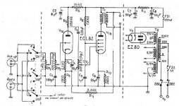
I was considering almost the same configuration, but without ECC83. Can I connect the input signal directly to ECL82's triode? I will use the amplifier with my laptop or smartphone. R33 is for Tone control, isn't it? And what do you think, how much power can I get from this amp?
Attachments
With R35 = 1M you need double the drive for the output tube, what is needed for the magic eye.To compensate for the loss that is where the extra triode comes in.
If R35=1k then 1 triode will do.But the eye doesn't do so well.
The output of a ECL82 is something like 3W.And yes R33 cuts more or less high notes.
Mona
If R35=1k then 1 triode will do.But the eye doesn't do so well.
The output of a ECL82 is something like 3W.And yes R33 cuts more or less high notes.
Mona
With R35 = 1M you need double the drive for the output tube, what is needed for the magic eye.To compensate for the loss that is where the extra triode comes in.
If R35=1k then 1 triode will do.But the eye doesn't do so well.
The output of a ECL82 is something like 3W.And yes R33 cuts more or less high notes.
Mona
I prefer the simple design, so the magic eye and ECC83 goes away, R35=1k and hope that is all. Hope, that the output transformer , that have been made by Philips has high quality and sounds as it should. By the way i have an amplifier from vintage German vinyl player with a single tube ECL86, that sounds great. Cheers!

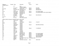
Thanks to Jeff Yourison, I am able to upload the files I mentioned earlier.
If the O/P transformers from the tape machines get reused, full pentode mode is the only realistic option. Open loop linearity in full pentode "finals" is maximized by regulating g2 B+ at a substantial fraction of anode B+.
If the O/P transformers from the tape machines get reused, full pentode mode is the only realistic option. Open loop linearity in full pentode "finals" is maximized by regulating g2 B+ at a substantial fraction of anode B+.
Attachments
Thanks to everybody, that take a part in this project ! I would like to keep the primary scheme, because the O/P transformer is quite specific, and I want to keep the power supply also. Of course there are unlimited options for different schemes, but the idea in the project is to use what I have, not to build something new. At this point with the help of Mona (Ketje) we have this scheme and I hope to hear and other opinions about is it possible to improve it with some small changes?
Attachments
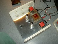
Anybody noticed in this old thread that the schematics and the R2R in the pic most probably don't relate? The schematics belongs to a Philips EL3541, aka RK 14, which is a one speed (3.75 in/s)/four track machine, while the pic shows a three speed device, which most probably needs three different equalizations. Also the manufacturer is another one, as yet stated in the title, and the Hornyphon shows an EM80 or EM85 instedad of an EM84.
Best regards!
Best regards!
- Status
- This old topic is closed. If you want to reopen this topic, contact a moderator using the "Report Post" button.
- Home
- Amplifiers
- Tubes / Valves
- ECL82 amp from old magnetophones
