Hi,
i am in the process with a new build, currently breadboarding and experimenting.
The main idea is to build a simple, secure SE-amplifier paralleling the two triodes power-pentode sections of the ECL805 and devise a driver with the two triodes. My design goals are to maximise the bandwidth my OPT permits, NFB≤12db, mainly H2 and H3 below 0.1% for normal listening.
Using the paint_kit tool (thanks to Dmitry) and trioded curves i found (thanks to Tom Schlangen) I set a working point that seems to fulfil my requirements. More to come when i am actually testing this later.
A german guy did a similar amplifierTrioden-SE mit der Roehre PCL805 von Frank Kneifel but it has to much NFB and the 2-stage driver is not to my liking. Anyway, it will provide a reference i intend to improve.
I will document my progress here, starting with the PSU, and will continue to design the power stage next.
Greetings, Harald
i am in the process with a new build, currently breadboarding and experimenting.
The main idea is to build a simple, secure SE-amplifier paralleling the two triodes power-pentode sections of the ECL805 and devise a driver with the two triodes. My design goals are to maximise the bandwidth my OPT permits, NFB≤12db, mainly H2 and H3 below 0.1% for normal listening.
An externally hosted image should be here but it was not working when we last tested it.
Using the paint_kit tool (thanks to Dmitry) and trioded curves i found (thanks to Tom Schlangen) I set a working point that seems to fulfil my requirements. More to come when i am actually testing this later.
A german guy did a similar amplifierTrioden-SE mit der Roehre PCL805 von Frank Kneifel but it has to much NFB and the 2-stage driver is not to my liking. Anyway, it will provide a reference i intend to improve.
I will document my progress here, starting with the PSU, and will continue to design the power stage next.
Greetings, Harald
Last edited:
Curves
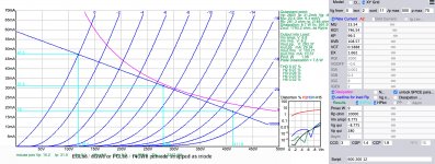
Here is the working point i selected for a start. If the simulation can be trusted, it has little H3 and the quiescent current x2 is just within the limits for the OPT i intend to use (ATRA0288 from "AskJanFirst")
Here is the working point i selected for a start. If the simulation can be trusted, it has little H3 and the quiescent current x2 is just within the limits for the OPT i intend to use (ATRA0288 from "AskJanFirst")
Attachments
Last edited:
PSU
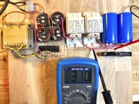
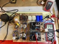
OK, here comes the schematic and shot of the breadboard for the PSU. As you see i go for an external AC of 13.4V that gets seeded to another 12V transformer resulting in almost 250VAC that gets rectified, first capaciatator bank, so one choke per channel and another smoothing cap with a film cap in parallel for better HF-performance.
The heating is done by simply rectifying the 13.4V, for the time being i use a buck converter that is set to 4x 6.3V with a current limit just above the 0.86A the filament draws when heated. I may change that to a discrete solution later, if RIF would be an issue.
Attachments

How do you expect to have 26.2 Vdc from a 13.4 Vac transformer winding via a bridge rectifier and a capacitor? I think you'd need a Delon or Greinacher voltage doubler for this purpose.
Best regards!
Best regards!
Sorry, my bad. I have been evaluating several tubes i have for this project and the ECL86 was among those.Be careful! ECL86 curves do't apply to ECL805!
Best regards!
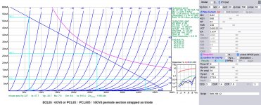
Here comes the right screenshot. As you can see, the ECL805 will achieve a higher Pout of almost 2W, the double of the ECL86. And at 1W output, the THD of both is virtually the same, 5-6% H2 and very little H3. But with the ECL805 i get another Watt on top, although with almost double the THD. The main drawbacks were the the higher Vq of -30V and the higher drive requirement of 30Vpp for the ECL805
But these present more welcome challenges and so i decided to go for paralleled ECL805.
Attachments
How do you expect to have 26.2 Vdc from a 13.4 Vac transformer winding via a bridge rectifier and a capacitor? I think you'd need a Delon or Greinacher voltage doubler for this purpose.
Best regards!
I cheated the cheap chinese way 😀 You can see the buck converter with cv and cc capability. I might go the voltage doubler route if i opt for a simple linear regulator for Vf and If later. I am a believer in heating up with current limitation, my old PCL86 SET ran with the same set of Ei-tubes for over 6years and just keeps going.
Attachments
Hello Harald, please read the entire text of my circuit. "Forward compensation" reduces the distortion. NFB doesn't have to be. Best regards, Frank
Hello Frank,
i guess you are the builder of the PCL805 amp i refered to? Really happy that you take interest in this thread. You seem to have a firm grip on amplifier design, i learned a lot from reading your pages. I did see the "Supra" configuration and this is definitely something i want to experiment with when i come to the power stage design.
Kind regards, Harry
Last edited:
Hello Harry,
yes i am the author of the article.
Every tube has its nonlinearities, I designed the circuit so that their nonlinearities largely cancel each other out
But already another transformer in the circuit requires the circuit to be retuned.
It also only works optimally with a linear impedance curve of the loudspeaker.
SUPRA triode is an ultra linear circuit with more than 100% negative feedback on the screen grid.
My tip is currently Frank Blöhbaum's MTA principle. Information on this is available in Linear Audio 6 and 8.
In my opinion, this is currently the best circuit concept in tube technology.
Best regards,
Frank
If an IH power amp needs DC for the heaters there are other problems. A needless complication.🙂
Last edited:
PSU and operating point
Happy holidays to everybody. Time to pick up threads again.
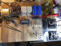
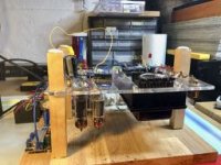
The first thing was to test the PSU. I made a base for the tubes and transformers on a piece of acrylic with stand-offs, wired heaters and 2 tubes per channel with bypassed cathode resistors as a simple test rig.
I am very happy how this works. I have a separate switch for the HV-transformer, so i can plug in, wait until the heaters are warmed up (the CC-LED from the heater supply turns of) and apply HV and make measurements. I have a red warning LED and one dedicated meter to warn me while things are dangerous.
I measured the B+ to 240V with each of the four tubes pulling 25mA of quiescent current with a 1k cathode resistor. An Iq of 25mA is what i am aiming for since the OPT i want to use have i Imax/2 of 50mA.
Out of curiosity i recorded DC-volt after the HV-rectifier for various loads to estimate the Ri of the PSU to be around 400Ohms. This seems kind of high to me, any informed input on that?
Happy holidays to everybody. Time to pick up threads again.
The first thing was to test the PSU. I made a base for the tubes and transformers on a piece of acrylic with stand-offs, wired heaters and 2 tubes per channel with bypassed cathode resistors as a simple test rig.
I am very happy how this works. I have a separate switch for the HV-transformer, so i can plug in, wait until the heaters are warmed up (the CC-LED from the heater supply turns of) and apply HV and make measurements. I have a red warning LED and one dedicated meter to warn me while things are dangerous.
I measured the B+ to 240V with each of the four tubes pulling 25mA of quiescent current with a 1k cathode resistor. An Iq of 25mA is what i am aiming for since the OPT i want to use have i Imax/2 of 50mA.
Out of curiosity i recorded DC-volt after the HV-rectifier for various loads to estimate the Ri of the PSU to be around 400Ohms. This seems kind of high to me, any informed input on that?
Attachments
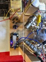
Apparently you are using magnetic ballasts meant for fluorescent lamps as PS chokes. I seriously doubt those are appropriate for tube amps. They may be quite noisy.
lamp ballasts as chokes
Hi,
that is true😱. The chokes, as many parts of the build are salvaged. The have thick laminations and the wire is likely wound all criss and cross on the bobbin and the width of the air gap is unknown😱. So yes, i agree with your point.
Still, from what i can measure now they perform their job (at 2.5H, 100Ohms) well and the residual AC on the B+ is just 18mV. We see how long they will allowed to be part of this build and if they get exchanged for something better later on.
Apparently you are using magnetic ballasts meant for fluorescent lamps as PS chokes. I seriously doubt those are appropriate for tube amps. They may be quite noisy.
Hi,
that is true😱. The chokes, as many parts of the build are salvaged. The have thick laminations and the wire is likely wound all criss and cross on the bobbin and the width of the air gap is unknown😱. So yes, i agree with your point.
Still, from what i can measure now they perform their job (at 2.5H, 100Ohms) well and the residual AC on the B+ is just 18mV. We see how long they will allowed to be part of this build and if they get exchanged for something better later on.
Last edited:
Heater supply
For the moment the cheap buck converter gives me peace of mind since i can with a glance see if the tubes have heated up sufficiently to apply HV 😎 to the circuit for the next round of measuring.
Furthermore, i want to use parts from the bin as much as possible for a build that is much about learning by playing with various configurations along the way😀.
If an IH power amp needs DC for the heaters there are other problems. A needless complication.🙂
For the moment the cheap buck converter gives me peace of mind since i can with a glance see if the tubes have heated up sufficiently to apply HV 😎 to the circuit for the next round of measuring.
Furthermore, i want to use parts from the bin as much as possible for a build that is much about learning by playing with various configurations along the way😀.
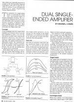
Dual Singel Ended Amplifier Graeme Cohen
There may be something useful in this paper by Graeme Cohen from 25 years ago🙂
There may be something useful in this paper by Graeme Cohen from 25 years ago🙂
Attachments
-
 Dual Singel Ended Amplifier Graeme Cohen p1.jpg532.7 KB · Views: 158
 -
 Dual Singel Ended Amplifier Graeme Cohen p2.jpg565.4 KB · Views: 157
 -
 Dual Singel Ended Amplifier Graeme Cohen p3.jpg573.3 KB · Views: 125
 -
 Dual Singel Ended Amplifier Graeme Cohen p4.jpg598.5 KB · Views: 127
 -
 Dual Singel Ended Amplifier Graeme Cohen p5.jpg684.1 KB · Views: 125
gm, Ra at operating point
I am intrigued by Pete Turner and the wealth of information he shares from a lifelong practice of commercial amp-building.
So, based on output-stage-SE-configurations i have been doing my best to measure some relevant parameters of the ECL805.
The operating point i use for now is 205V anode-cathode, Vbias at -24.7V by Ia 24.7mA over a 1k bypassed cathode resistor.
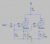
I managed to measure GM for trioded operation (se following schematic for the test rig)
gm_g1: 3.25mA/V
(2.44V over Rtest 100R for 2 tubes => 24.4mA/2 = 12.2mVA for vin of 3.75V, e.g. 3.25mA/V)
I failed to measure Ra the "Turner-way", will discuss this in a new post.
I am intrigued by Pete Turner and the wealth of information he shares from a lifelong practice of commercial amp-building.
So, based on output-stage-SE-configurations i have been doing my best to measure some relevant parameters of the ECL805.
The operating point i use for now is 205V anode-cathode, Vbias at -24.7V by Ia 24.7mA over a 1k bypassed cathode resistor.
I managed to measure GM for trioded operation (se following schematic for the test rig)
gm_g1: 3.25mA/V
(2.44V over Rtest 100R for 2 tubes => 24.4mA/2 = 12.2mVA for vin of 3.75V, e.g. 3.25mA/V)
I failed to measure Ra the "Turner-way", will discuss this in a new post.
Attachments
There may be something useful in this paper by Graeme Cohen from 25 years ago🙂
Wow, thanks a million

- Home
- Amplifiers
- Tubes / Valves
- ECL805 parallel SET build