old AGC circuit
This is from D. Nührmann, Industrielle Schaltungstechnik (again gif disguised as zip). The output signal is AC-coupled via the 2.2 uF capacitor to the AA143 germanium diode. It will clamp the negative excursions, while the positive excursions charge the 220 uF + 12 nF capacitors through the 39 k resistor. The op amp will control the tail current in trying to balance its inputs. The amplitude is set by controlling the reference voltage on the non-inverting input.
Is the AA143 adequate for HF clamping? Is there a more suitable replacement, i.e. a HF Schottky diode? Is there a simpler AGC circuit?
Thanks,
Eric
Attachments
Been watching this thread casually, and I am planning to work on a schematic for a low-noise oscillator that uses NPN transistors, so it will be easier to build.
Recommendations on program to use that will let me post a readable schematic? (I never use schematic capture........too old to care about learning something that new.) [joke]
Jocko
Recommendations on program to use that will let me post a readable schematic? (I never use schematic capture........too old to care about learning something that new.) [joke]
Jocko
Jocko, I find MicroCap to be absolutely wonderful for drawing schematics. It a very powerful simulator etc. but also very suitable for schematic drawing. There is a demo version available, with no time limitation and 50 part simulation restriction, but there is no restriction in just schematic drawing.
I have tried many such programs and MicroCap is in my opinion by far the easiest and most intuitive to use as circuit drawing tool. There are also nice tutorial scripts that get you running in no time 🙂
http://www.spectrum-soft.com
Check the JLH amp thread for sample schematic made with MicroCap
http://www.diyaudio.com/forums/showthread.php?threadid=3075&perpage=15&pagenumber=4
UHH. Hope you forgive me for such preaching 🙂
Ergo
Preach on.
Let's see if I can upload this kludge schematic made a different way.
Nope too big. I have a .gif of it if anyone is interested. Email me.
Jocko
Let's see if I can upload this kludge schematic made a different way.
Nope too big. I have a .gif of it if anyone is interested. Email me.
Jocko
OK......now it is my turn to be the idiot..........
How do you save this in a format that will be accepted here?
Jocko
How do you save this in a format that will be accepted here?
Jocko
Let's try it again.......
This originally appeared in EDN in 5/73. I have seen it several places, including the ARRL Handbook.
The trick about this is that the crystal acts as both a low-pass, and sideband filter. This version is 11.2896 MHz. C4 should be about 680 pF, but I increased it to keep the harmonics down in Q3. Probably could have done the same by playing with R11, but I just grabbed the handiest values around. That way anyone should be able to build it.
I did not include the power supply decoupling capacitors. I leave that part up to your discretion.
Attachments
Phase noise and implementation
Hey all:
In wireless/telecom circles where I wear my golden handcuffs, the Colpitts topology is widely regarded as the most straightforward low phase noise osc: if you want clean, do a differential jfet colpitts and feed it to a high speed comparitor is the word I have been hearing. Having ignored a number of subtle hints, and finally listening to Elso, I heated up the slobbering iron, and dove in a built a couple. So far, wow. Night and day sonic improvement over stock CMOS and comparitor oscs replaced.
There are still issues, largely implementation. The comparitor does not swing high enough with a 5 volt supply, so it has a 6.25 volt supply to swing 5 volts. When driving even a single CMOS/TTL load, the comparitor "causes" sufficient ground bounce to create glitches in the Colpitts sine and sine bar outs, jfet sources. Mostly common moded out, but I still don't like them. Yes, even with rf scope probes. Version three will have a split ground plane. Maybe it will be ready for primetime.
Sorry for the fuzzy sch, had to squeeze it to fit. Source resistors are 475r, gate resistors are 10M, comp snubber resistors are 100r, top cap is 47p, bottom cap is 100p.
Not in sch are bypass caps galore. Jfet supply is an LT1021, comp supply is an LT1086. Built "3D" on a copper foil ground plane. XTAL is sorbothane mounted, as is whole assembly. Caps are silver-mica, jfets are 2n5457s for now, matched Idss of 4 mA, comp is MAX1116 for now. Jfets draw ~~2mA ea in circuit, source voltages ~~0.8v.
Enjoy...
WMS
Attachments
Jocko,
could you elaborate on how your comment that the crystal works as both low pass as well as side band filter? I seem to have trouble understanding circuits that were divised in the 70s when engineers were still thinking in tubes...
Does Q1 act as a free-running oscillator?
Puzzled,
Eric
could you elaborate on how your comment that the crystal works as both low pass as well as side band filter? I seem to have trouble understanding circuits that were divised in the 70s when engineers were still thinking in tubes...
Does Q1 act as a free-running oscillator?
Puzzled,
Eric
Problem with JFETs is that they don't have enough transconductance to really drive the crystal hard. Diff pair might get the drive a bit higher.
My telecom days are over. At least for now. Which also means I do not have access to MY H-P phase noise setup.
Ther signal is picked off from the 22 ohm resistor. It has to go through the crystal to get there. Neat idea. Wish I had thought it up.
Jocko
My telecom days are over. At least for now. Which also means I do not have access to MY H-P phase noise setup.
Ther signal is picked off from the 22 ohm resistor. It has to go through the crystal to get there. Neat idea. Wish I had thought it up.
Jocko
Anybody have a foolproof way to measure phase noise? I have a good number of high bandwidth real time sampling scopes around but I have the feeling I cannot trust their clocks and converter aperture jitter....
Eric
Eric
more stuff
Yikes, the next attachment will be less fuzzy...looks like a lot of monolithic opamps sound to me...
Hey, this board is very refreshing, seems very civilized ... an open sharing of ideas with a minimum of flames and egos.
Looking forward to posts of sonic results with various osc topologies.
Oh, yes...jfets are also known to suck in terms of 1/f noise, but whatever spectra they exude, seem to work well as a Colpitts. The idea is that one does not need a lot of gain, just enough to overcome entropy and keep the tank ringing. It is normal to wonder WTF when first looking at a Colpitts! The differential arrangement relies on intentional injection locking for once, which happens out of phase. The signal level could be higher if one biases the gates above ground, but that would introduce power supply coupling which in my book is evil.
Hoo boy, measuring phase noise is an art unto itself. Spectrum analyzers with low noise options are the best bet for such freq domain measurements. In the time domain, fast scopes can only be of marginal use. One chip house I know of uses old fashioned analog storage scopes and, get this, a magnifying glass, but is limited to levels around a couple hundred pS of jitter.
As Elso et al have gently pointed out, the ears are a wonderful instrument. The tools won't specifically lie to you, just won't tell the you the whole truth. I can hear deliberately induced thermal tails and supply induced grunge quite easily with familiar music on a familiar system, but trying to measure them is like splitting hairs. I'd rather grok what the circuit is doing and optimize by ear, but that is just me...
Enjoy,
WMS
Drew it a different way........forgot C8 too.
If you short R4/C4, and connect the left side of C5 to the dashed lines (which don't show up now!), it looks like any other oscillator.
The only way is with a phase noise setup. I guess you good build one with if you already had a low-noise oscillator, mixer, and spectrum analyzer.
Jocko
If you short R4/C4, and connect the left side of C5 to the dashed lines (which don't show up now!), it looks like any other oscillator.
The only way is with a phase noise setup. I guess you good build one with if you already had a low-noise oscillator, mixer, and spectrum analyzer.
Jocko
Attachments
ECL Schematics and more
Eric,
Nice design with ECL receivers, and it reminds me of a sch. that can be found on http://www.euroquartz.co.uk/pdf/application-notes.pdf (page 2). I'm no sure you really need the cap 'cross the inputs, but it is safer. Maybe your parasitic oscillations are related to the "real" circuits stray inductances and capacitances. Have you tested it with SMT parts, including the crystal itself ?
Concerning oscillators, I've been busy toying with various designs to plug into my CD player. Most of all led to improvements, but the best ones ('til now 😉 ) were Elso's KWAK/Colpitts clock and a schemo I borrowed from an old Elektor magazine (common base Butelr XO). On both designs, I've tested two output stages, one with a fast comparator (AD8561) and an ECL stage (MC10ELT21) as per as AD's application note AN419 ( http://www.analog.com/library/applicationNotes/oscillators/an419.pdf )
(Yes, Elso, I've given up with the dual-gate mosfet buffer - you were right, as usual 😉 )
On a scope, all the designs had quite the same characteristics (rise time, levels, etc...), but the ultimate musical tests gave surprising results :
- Elso's clock was slightly better with AD8561 output stage
- Butler common base was better with ECL stage...
And finally, I was unable to hear a difference between the two designs (each one with the right output stage) ... And both clocks make wonderful music, with a lot of space, great bass, full of air and details.
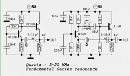
For the interested ones, I've attached the schematics of the Common Base Butler XO. It needs a series resonant Xtal, but frequency can be slightly trimmed with the variable cap (which can be removed if needed). The left schemo is the basic (but working) one, and the right one is improved a little bit with diode clamping and a much better insensivity to power supply variations, but at the cost of a larger part count. As far as I have tested, you don't have to change any component value if you change the Xtal frequency.
Any comments/improvements welcome.
Greetings,
Eric,
Nice design with ECL receivers, and it reminds me of a sch. that can be found on http://www.euroquartz.co.uk/pdf/application-notes.pdf (page 2). I'm no sure you really need the cap 'cross the inputs, but it is safer. Maybe your parasitic oscillations are related to the "real" circuits stray inductances and capacitances. Have you tested it with SMT parts, including the crystal itself ?
Concerning oscillators, I've been busy toying with various designs to plug into my CD player. Most of all led to improvements, but the best ones ('til now 😉 ) were Elso's KWAK/Colpitts clock and a schemo I borrowed from an old Elektor magazine (common base Butelr XO). On both designs, I've tested two output stages, one with a fast comparator (AD8561) and an ECL stage (MC10ELT21) as per as AD's application note AN419 ( http://www.analog.com/library/applicationNotes/oscillators/an419.pdf )
(Yes, Elso, I've given up with the dual-gate mosfet buffer - you were right, as usual 😉 )
On a scope, all the designs had quite the same characteristics (rise time, levels, etc...), but the ultimate musical tests gave surprising results :
- Elso's clock was slightly better with AD8561 output stage
- Butler common base was better with ECL stage...
And finally, I was unable to hear a difference between the two designs (each one with the right output stage) ... And both clocks make wonderful music, with a lot of space, great bass, full of air and details.
For the interested ones, I've attached the schematics of the Common Base Butler XO. It needs a series resonant Xtal, but frequency can be slightly trimmed with the variable cap (which can be removed if needed). The left schemo is the basic (but working) one, and the right one is improved a little bit with diode clamping and a much better insensivity to power supply variations, but at the cost of a larger part count. As far as I have tested, you don't have to change any component value if you change the Xtal frequency.
Any comments/improvements welcome.
Greetings,
Attachments
High Frequency clock for asynchronous recloking
Hi again 🙄
I forgot in my previous post to mention some experiments (Maybe off-topic here) I made with high frequency oscillators (96-98 MHz) for asynchronous reclocking in DACs (see http://www.diyaudio.com/forums/showthread.php?s=&threadid=1594 for a start point) . To sum up, the idea is to use D flipflops just before the DAC chips to reclock the digital stream using an asynchronous high frequency clock. I'm completely unable to technically explain what happens to the sound when doing so, but I wanted to test it.
To jump to the conclusion, I don't know how it does, but it works ! The improvement gap is not as large as when I first plugged a high quality clock in my CD player, but the improvement is here. How to qualify it ? IMHO, it reduces harshness, making the sound more "analog". But it's only one day old , and I haven't had enough time to perform careful listening tests... more to come...
But back to the off-topic topic 😛 of this thread. The most challenging part (for me) of this little project was to find a high quality 96-100MHz clock to feed the FFs. I've tested various designs I found in litterature : Analog Devices' AN-419 Butler XO, Butler common base C-Tap, Butler Emitter Follower, Pierce, Harmonic ECL... If you're interested, I can post schematics/links.
All these designs were buffered by an AD8611 ultra fast comparator or by the now-classical MC10ELT21 ECL IC. I finally settled on the ECL IC, which gave better results, as well on the scope as in my ears.
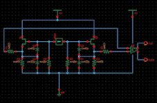
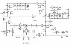
And last but not least, I've attached the schematics of the XO I found to be the best IMHO, in terms of stability, ease of startup, simplicity...and sound (for the moment). It's called the emitter coupled harmonic XO. May be the three adjustement points can frighten you, but it's very tolerant, and once trimmed, it will always start.
Feel free to test and comment it.
Hi again 🙄
I forgot in my previous post to mention some experiments (Maybe off-topic here) I made with high frequency oscillators (96-98 MHz) for asynchronous reclocking in DACs (see http://www.diyaudio.com/forums/showthread.php?s=&threadid=1594 for a start point) . To sum up, the idea is to use D flipflops just before the DAC chips to reclock the digital stream using an asynchronous high frequency clock. I'm completely unable to technically explain what happens to the sound when doing so, but I wanted to test it.
To jump to the conclusion, I don't know how it does, but it works ! The improvement gap is not as large as when I first plugged a high quality clock in my CD player, but the improvement is here. How to qualify it ? IMHO, it reduces harshness, making the sound more "analog". But it's only one day old , and I haven't had enough time to perform careful listening tests... more to come...
But back to the off-topic topic 😛 of this thread. The most challenging part (for me) of this little project was to find a high quality 96-100MHz clock to feed the FFs. I've tested various designs I found in litterature : Analog Devices' AN-419 Butler XO, Butler common base C-Tap, Butler Emitter Follower, Pierce, Harmonic ECL... If you're interested, I can post schematics/links.
All these designs were buffered by an AD8611 ultra fast comparator or by the now-classical MC10ELT21 ECL IC. I finally settled on the ECL IC, which gave better results, as well on the scope as in my ears.
And last but not least, I've attached the schematics of the XO I found to be the best IMHO, in terms of stability, ease of startup, simplicity...and sound (for the moment). It's called the emitter coupled harmonic XO. May be the three adjustement points can frighten you, but it's very tolerant, and once trimmed, it will always start.
Feel free to test and comment it.
Attachments

Wenzel Associates Inc have a page on "Techniques for Measuring Phase Noise"
Also thought I'd add the high-end clock from elektor from a few years ago.
Schematic was done with Proteus-lite from <a href="http://www.labcenter.co.uk/">www.labcenter.co.uk</a>, free with some limits but very useable.
Regards
James
Also thought I'd add the high-end clock from elektor from a few years ago.
Schematic was done with Proteus-lite from <a href="http://www.labcenter.co.uk/">www.labcenter.co.uk</a>, free with some limits but very useable.
Regards
James
Attachments
Modifications to the KWAK-CLOCK
Hi Wildmonkeysects,
I builded your modification with two FET's. Strictly speaking this is no longer a Colpitts oscillator. However I adhered to the original parts and values of the KWAK-CLOCK i.e. J309 and AD8561. The crystal was "hung" by two 10pF caps between the gates of the FET's. I did not have the problems you encountered; it worked right away. Sonically the result was <B>exactly</B> the same as the original KWAK-CLOCK.
I also builded a version of the KWAK-CLOCK with just a J309 FET added with 1M gate biasing ad 1k source resistor. Source connected to the - input of the comparator. Again this works but sonically no difference to the original circuit.
You are using a different FET and LT1116 comparator [probably misspelled as MAX1116 which is a 8 bit DAC]. As I experienced it does make a big difference which FET and comparator are being used; I strongly encourage you to get a J309 and AD8561 as these produce the best results. I have been using the 2SK117BL and LT1016 with worse results.
From Rudolf Broertjes I got the suggestion to add a large 6800µF capacitor across the clock supply. Though very sceptical about this mod I tried a 10000µF electrolytic I had laying around. This mod produced a slightly better bass and slightly more open soundfield. I don't have a explainnation for this result; lower noise on the supply? I am using a LT1086-5 for the clocksupply.
Also builded various supplies like LT1021-5 reference and OP27 opamp in a Walt Jung like regulator, BC550C/TL431 series regulator with PI-filter in front of it. The latter produced a soundpicture slightly more "at ease". I did not like the Jung regulator in this application and still prefer the LT1086-5 or the LT1086; with bypassed adjustment pin; used for the supply of the CDP; in my setup.🙂
2SK117BL? Are my eyes playing tricks on me again?
I need to find the schematic of this thing........
Jocko
I need to find the schematic of this thing........
Jocko
KWAK-CLOCK Schematic/2SK117BL
Hi Jocko,
Stirring things up again......?!
Schematic sent!
I choose the 2SK117BL initially because it was laying around and is very low noise. People keep reminding me noise= phasenoise=jitter.
I am not so sure of this simple relationship.🙂 😉
Hi Jocko,
Stirring things up again......?!
Schematic sent!
I choose the 2SK117BL initially because it was laying around and is very low noise. People keep reminding me noise= phasenoise=jitter.
I am not so sure of this simple relationship.🙂 😉
simulating oscillators
There are a lot of cookbook recipes like preserve Q, use FETs, use low noise AF transistors, use very sinusoidal drive, ...
However, when it comes to optimizing a given circuit or deciding whether one circuit is better than another, it is not clear which of these points will be the most important in a given application.
I particular, it seems to be very unclear of what the effective Q of a crystal inside a circuit is.
Might this be a way to simulate Q: simulate the oscillator, inject some sinusoidal of various frequencies close to the fundamental into on lead of the crystal using a high-value resistor and see how much of this signal is rejected by the circuit?
Puzzled,
Eric
Eric:
Just got around to fully reading your post of 2/28.
The reason you don't want an active device with too high Ft is that there will be more parasitics. So chose the slowest one that is fast enough.
JFETs do have lower noise, which is good, but they ususally don't have enough gain to drive the crystal hard enough. I've built RF circuits with audio transistors, many times, and have always gone back to the RF types. I needed the gain.
Power supply noise is probably a bigger contributor of phase noise than the active device.
Somewhere I have a good book on oscillators. I seem to recall the author feeling that using JFETs for the lower Q loading was overrated.
Jocko
- Status
- Not open for further replies.
- Home
- Source & Line
- Digital Source
- ECL oscillator just won't oscillate