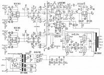
Hey all. Replaced the two of the PS filter cans with two new 100uF caps. Wired it exactly the same, as far as I can tell. The difference, as the schematic shows, is that instead of two internal caps wired in parallel, the new caps are each 100uF.
After the swap, two things happened. Immediately, R89 started getting really hot ... to the point of smoking. Now it doesn't smoke, but gets got. Which is just weird.
Also, the filament voltages on everything in the H1 circuit are really low, like half normal (3.1). Voltage on the power tube heaters are also low (5.1).
Needless to say, it sounds like ****. Any thoughts? I know I'm missing something obvious, as I'm not particularly good at this.
Thanks!!
Attachments
Pull the rectifier tubes and verify that the OA150 is not bad, this is your bias rectifier. It should probably be replaced along with the 50uF/25V electrolytic in the bias supply.
Make sure nothing is wired backwards and there are no HV shorts.
Where did you connect the grounds on the new filter caps?
Do you have a variac or ballast lamp (for some reason sometimes referred to as a dim bulb tester around here!) for safely testing while you trouble shoot for PSU issues?
Make sure nothing is wired backwards and there are no HV shorts.
Where did you connect the grounds on the new filter caps?
Do you have a variac or ballast lamp (for some reason sometimes referred to as a dim bulb tester around here!) for safely testing while you trouble shoot for PSU issues?
I will check the rectifier and replace the bias supply caps. I'll update on that front ...
I don't believe anything is wired backwards. Ground for the previous caps was on the top-side of the amp ... two black wires bussed across two tabs connected to the case of the can. For the new caps, I took one each of the black wires and soldered them to the ground lugs. Correct, right?
I don't have a variac ... wish I did. I could make a lamp. I know that would be infinitely smarter.
One interesting thing: the ground lug of one of the caps measures about 16kOhm to ground while the other measures 0. Shouldn't they both be 0? I feel like I screwed up the grounding somehow...
As Kevinkr wrote; remove tubes 10 and 11.
You should go a step further and remove all the tubes.
Now there is no load on the secondaries of the transformer apart from the bias circuit pf the output tubes.
If that is ok or restored to the values in the schematic, you can proceed with the rest.
Measure the voltages and use them as a reference for the next step.
Do not insert the rectifier tubes tight now!!!!!!
Insert the preamp and measure the H1 voltages.
OK, proceed. NOK, find the problem in one of the heaters of these tubes.
Next;
Insert the power tubes and check H2.
OK, go on.
NOK, check for a problem in the heaters of these tubes.
A small and usefull triick:
Do you have a 2 x 30V adjustable supply with current limiter?
That's 60V in series. (1 x 30V will do also)
Switch of the amp. Do not reconnect to the AC outlet!!!!!!!!!
Connect the (+) to the plus of C34.
Connect the (-) to the ground.
Do you have the 60V (or 30V) on te anodes of the power tubes?
What voltages do you have at the positive side of C35, C36, C37?
If all that is ok, remove your power supply.
Reinstall the rectifier tubes.
Use a lamp (40..50W) in series with the ac connection of the amp.
Switch on the amp.
Measure the high voltages, the bias voltage, the heater voltage.
Should be ok..
If al is ok; clean the pots and enjoy the amp.
R89 supplies the -VE bias voltage and there is only a 10k load so check C25 is in the correct way around with no shorts!
One interesting thing: the ground lug of one of the caps measures about 16kOhm to ground while the other measures 0. Shouldn't they both be 0? I feel like I screwed up the grounding somehow...
Yes, they should both be 0.
In addition this the power transformer is multi-voltage make sure that during all of the work done that the voltage selector did not somehow end up in the wrong position. (Does not explain all of the symptoms but might explain the low filament voltage or not.. See recommendations in post #5 above.)
If you replaced the bias filter cap (C25) the recommendation in post #6 is valid too. Definitely check for shorts in bias supply..
Thank you for all the advice. Am in the midst of applying it.
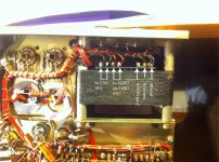
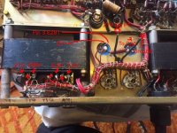
Am noticing what seems to be a problem. When I measure continuity between the transformer lug labeled "ground" in the attached image and the chassis, there is none there. With all tubes out I measure and the unit plugged in, I measure about 23V AC on this lug. Shouldn't it be 0? Is there a short in my PT?
Am noticing what seems to be a problem. When I measure continuity between the transformer lug labeled "ground" in the attached image and the chassis, there is none there. With all tubes out I measure and the unit plugged in, I measure about 23V AC on this lug. Shouldn't it be 0? Is there a short in my PT?
Sorry...here's the image
Image attached. I'm talking about the far right lug in the image. Measuring 20ish volts AC on this and no continuity with ground.
Image attached. I'm talking about the far right lug in the image. Measuring 20ish volts AC on this and no continuity with ground.
Hi,
are you sure that lug is ground?
Is it not the -V bias voltage?
Check where that wire is going to.
Also check if you can find another ground lug on the transformer.
Let us know.
are you sure that lug is ground?
Is it not the -V bias voltage?
Check where that wire is going to.
Also check if you can find another ground lug on the transformer.
Let us know.
This should help
Thanks, Tarzan. No, I'm definitely not sure of anything. Clearly. Ha.
Here's what happens:
I get continuity between that lug (and it's associated wire) to ground. That wire was also the one soldered to a lug on the case of one of the original filter caps I removed, so it sure seems like it supposed to be ground.
When I turn on the amp w/ all tubes removed, I measure about 21-23V AC on that lug.
So, where should the wire connected to that lug go w/ respect to my new filter caps? Each 100mF cap has two lugs. There are two black wires that were previously grounded to the old filter caps. One is connected to a grounding bus that runs along the output tubes. The other is connected to this lug on the PT.
Should each wire go to a separate ground lug on the new filter caps? Does it matter?
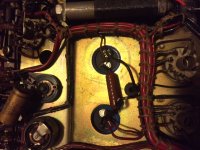
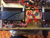
I have attached an image showing where all the associated PS wiring goes. Black indicates what I believe to be ground. The two red wires on the left side go one each to the cathodes of the rectifier tubes. The other goes to Pin 1 of "Ro. 2".
BTW, am consistently getting 6.3V on preamp filaments if I adjust R91. Sweeping the pot varies the AC voltage between 3ish and 7ish
Thanks, Tarzan. No, I'm definitely not sure of anything. Clearly. Ha.
Here's what happens:
I get continuity between that lug (and it's associated wire) to ground. That wire was also the one soldered to a lug on the case of one of the original filter caps I removed, so it sure seems like it supposed to be ground.
When I turn on the amp w/ all tubes removed, I measure about 21-23V AC on that lug.
So, where should the wire connected to that lug go w/ respect to my new filter caps? Each 100mF cap has two lugs. There are two black wires that were previously grounded to the old filter caps. One is connected to a grounding bus that runs along the output tubes. The other is connected to this lug on the PT.
Should each wire go to a separate ground lug on the new filter caps? Does it matter?
I have attached an image showing where all the associated PS wiring goes. Black indicates what I believe to be ground. The two red wires on the left side go one each to the cathodes of the rectifier tubes. The other goes to Pin 1 of "Ro. 2".
BTW, am consistently getting 6.3V on preamp filaments if I adjust R91. Sweeping the pot varies the AC voltage between 3ish and 7ish
Attachments
Well, I have such a feeling that something is not correct.
Was the amp in working order when you changed the caps?
I worked a lot on Dynacord equipment and I can't see why echolette should place a ground lug there and the bias lug on another side of the transformer.
Before you continue; Where is the lug for the bias voltage?
For the moment I believe that the "grounding" lug you are pointing to is the bias lug.
Find the R89 etc.
Trace down the wire back to the transformer.
Only if all secondaries are identified you should continue.
At the moment I do not care about measurements and so on.
Identify the secondaries.
Find the middle connection of the high voltage secondary.
No load whatsoever.
Connect your meter to that point.
Measure the ac voltage of the windings of that secondary.
Then come back.
I have to go now; it's 23:20 here in Belgium.
I'll be back tomorrow.
Cheers
Just seems like the two relevant lugs are somehow swapped? The one I'd expect to provide 21V for the output bias supply is instead measuring 0, and the other, larger, ground-looking wire is measuring 21V.
Anyway, attached is a diagram of what's what. Hope it isn't too confusing, and thank you everyone for your help.
Anyway, attached is a diagram of what's what. Hope it isn't too confusing, and thank you everyone for your help.
Attachments
Are you sure that tap was not originally grounded through the capacitor cans? Were they actually isolated from the chassis? If you have not moved the connections anywhere else the problem by definition lies with what you have done; the amp worked in the past as wired. (And were they bused together cap to cap?)
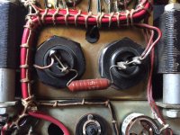
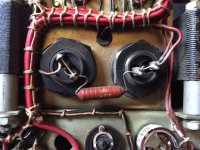
Not sure which tap you're referring to specifically, but as far as I can tell, the tap from the far left in the image (the one reading 21V) was attached (via the black wire) to a stiff straight metal wire that was itself attached to a tab on the capacitor can. The wire connected these tabs, with the other black wire in the image (the one definitively connected to ground) also soldered to it.
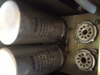
Each original capacitor can had two lugs on the underside, which i assume to be + for each of the 50uF internal capacitors and an external lug which I assumed to be ground. The two tabs on the underside were also hardwired together on each capacitor. The attached images should make this all easier to understand.
And most definitely the current problems have something to do with what I've done. Of that, I am most definitely sure. :-(
The problems definitely started when I replaced the two PS filter caps. While they only have a + and - lug on them, I thought I duplicated the wiring of the original otherwise. Obviously I had to bring those two black wires from the topside of the chassis to the bottom. I'm just confused why one of them is connected to a lug on the PT that reads 21V but seems to have been originally connected to ground?
Anyway, all advice appreciated! I'm learning ... slowly but surely.
Attachments

it looks like a simple problem... the only thing you did different was hook the grounds up to a different spot.... to correct the problem,, hook up the grounds where they were hooked before and check the value of the resistor that was smoking and replace if needed... ... (BOTH CAPS ON THE NEG SIDE SHOULD READ 0 OHMS TO GROUND..)
THE NEG CONNECTION ON BOTH CAPS HOOK TO GROUND..
all should be normal...
THE NEG CONNECTION ON BOTH CAPS HOOK TO GROUND..
all should be normal...
Have you put a jumper between the two lugs + and - on the new capacitors? that's what it looks like.
So this original jumper wire (visible on the top of the chassis pic) connecting the grounds is relevant somehow to the proper function of the amp? I thought it was just a matter of convenience. Would love to know more about that...
Jeffhigh, not sure what you mean? The originals are jumpered, but I thought that's b/c both lugs on the old caps are +. the new caps have only two lugs, + and –.
Thanks all.
Jeffhigh, not sure what you mean? The originals are jumpered, but I thought that's b/c both lugs on the old caps are +. the new caps have only two lugs, + and –.
Thanks all.
- Status
- Not open for further replies.
- Home
- Live Sound
- Instruments and Amps
- Echolette M40 Cap job ... now everything sucks