hi,
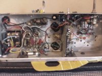
I've been working on a 1954 radiogram chassis simplifying it by removing the radio components and replacing faulty parts to use as a mono PU amplifier.
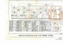
there is a schematic for it, but am having trouble following the switching diagram.
V1, V3, and V8 tubes are removed and only half of the ech81 (V2) is used
I have been marking out the schematic the parts of the circuit to keep intact though are unsure about a few area's. i'm not sure about what components to leave and the wiring between V2 and V4.
also i'm not sure if T1 and T2 need to be connected for it to work as a PU amplifier?
any help would be great if anyone is familiar with these designs and switch schematics from the mid 1950's
ps. V6 is in use, the wiring is ment to be colored orange too.
thanks
I've been working on a 1954 radiogram chassis simplifying it by removing the radio components and replacing faulty parts to use as a mono PU amplifier.
there is a schematic for it, but am having trouble following the switching diagram.
V1, V3, and V8 tubes are removed and only half of the ech81 (V2) is used
I have been marking out the schematic the parts of the circuit to keep intact though are unsure about a few area's. i'm not sure about what components to leave and the wiring between V2 and V4.
also i'm not sure if T1 and T2 need to be connected for it to work as a PU amplifier?
any help would be great if anyone is familiar with these designs and switch schematics from the mid 1950's
ps. V6 is in use, the wiring is ment to be colored orange too.
thanks
Attachments
Last edited:
to view image better, first click attached thumbnail then >>>> right click image and select 'view image' then >>>> use 'CTRL' and + or - keys to zoom in and out.
or instead of selecting 'view image' you can 'save image' and view in your own image viewer. Hope that is helpful
or instead of selecting 'view image' you can 'save image' and view in your own image viewer. Hope that is helpful
V2 (ech81) triode section does have a dual function on this schematic. On most tube radios, this tube only works as frequency changer (mixer/oscillator). On this radiogram, it also works as additional audio frequency amplifier for the PU input. It probably picks a significant amount of background noise and hum doing this job, this is the reason why most radiograms aren't wired this way. I would try to remove V2 and connect the input to C47 directly. If additional amplification is needed, you may rebuild the V2 stage as standard RC coupled triode amplifier.
Beside removing the Tuner circuits. You will need to adjust the voltage dropping resistors (ie. R35,R29) to account for the lower current draw.
Just a suggestion, to improve and avoid unseen problems, I would remove everything left of R16 pot and replace in place a better known pre-amp and tone stack circuit.
Just a suggestion, to improve and avoid unseen problems, I would remove everything left of R16 pot and replace in place a better known pre-amp and tone stack circuit.
The audio frequency amplifier of this radiogram is a classic European tube radio schematic of that era. The goal is not Hi-Fi reproduction, but rather a "pleasant sound" and clear radio reception. Tone controls contribute to the overall vintage sound and I would not change them. If a Hi-Fi-like audio quality is required, then the power supply and all the audio amplifier should be reworked. As example, a different global feedback scheme must be implemented. On the original schematic, the feedback is connected to the cold side of the volume control R16: this means that the feedback does change while turning the volume control. When the volume is at maximum, the feedback is reduced: this will increase the gain and cut low and high frequencies, to optimize the reception of weak radio signals. On this radio the R17 has low value so the effect is not extreme but it should be still noticeable. A filter choke on the power supply will reduce hum. There is no need to compensate for the lower B+ draw due to the removal of the radio frequency section. On several radiograms of this era, the B+ to the RF section was purposefully cut by an auxiliary contact on the source selector when operating as record player, to boost the B+ and therefore increase the output power.
It might be a good idea if you tell us what it is you are actually going to use as an input.
''PU amplifier'' is that an old ceramic/crystal cartridge, a modern moving magnet cartridge or something else?
''PU amplifier'' is that an old ceramic/crystal cartridge, a modern moving magnet cartridge or something else?
Last edited:
hi,
thanks for replying only just had a chance to look at it again.
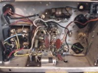
my main goal was try get rid of some of the buzz by shortening the long un-shielded PU input wiring through the switches. there isnt much hum from the unit, just buzz. i replaced the PS capacitors to get it going.
Im wanting to keep it sounding the same the same so will try to keep the original parts.
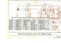
I removed the switch board with alot of the radio components on and traced the PU input path. here is the schematic for more what unit is like now
thanks for replying only just had a chance to look at it again.
my main goal was try get rid of some of the buzz by shortening the long un-shielded PU input wiring through the switches. there isnt much hum from the unit, just buzz. i replaced the PS capacitors to get it going.
Im wanting to keep it sounding the same the same so will try to keep the original parts.
I removed the switch board with alot of the radio components on and traced the PU input path. here is the schematic for more what unit is like now
Attachments
Last edited:
hi, two inputs with selector switch, one audio line level and another for a dynamic microphone.It might be a good idea if you tell us what it is you are actually going to use as an input.
''PU amplifier'' is that an old ceramic/crystal cartridge, a modern moving magnet cartridge or something else?
yes I agree very good 50's sound original. Thanks for the other info too.The audio frequency amplifier of this radiogram is a classic European tube radio schematic of that era. The goal is not Hi-Fi reproduction, but rather a "pleasant sound" and clear radio reception. Tone controls contribute to the overall vintage sound and I would not change them.
Ah yes, i have changed and shortened the input to V2 and removed all the switches seem to have more buzz now. though the inputs are not behind the shielded partition now. i have a feeling the tubes a very well used, i had to swap the ech81 to get it working properly but i am still getting buzz and a bit of surf noise. have to get another couple of ecb41's to try in place.V2 (ech81) triode section does have a dual function on this schematic. On most tube radios, this tube only works as frequency changer (mixer/oscillator). On this radiogram, it also works as additional audio frequency amplifier for the PU input. It probably picks a significant amount of background noise and hum doing this job, this is the reason why most radiograms aren't wired this way. I would try to remove V2 and connect the input to C47 directly. If additional amplification is needed, you may rebuild the V2 stage as standard RC coupled triode amplifier.
hi, two inputs with selector switch, one audio line level and another for a dynamic microphone.
In which case try pcan's suggestion and use C47 as your input point. Remove V2 all together. Does the buzz go away if you short the left side of C47 to ground?
Last edited:
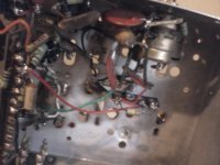
This is a very unusual schematics, regarding the »PU« operation. As any passive components that, at first glance (see your 2nd pic), appear to be in the audio path, are either high-ohmish resistors or low-pF capacitors, I suspect the ECH81 triode being also an oscillator then that is amplitude modulated by the PU input signal. The resulting RF signal is demodulated by the left diode in the first EBC41 and amplified by the radio's AF section, beginning with the triode in this tube. But I could as well be wrong, 'cause the rotary switches' function remain somewhat unclear to me.
My interpretation would explain the buzz issue, though, as a result of that many sources of RFI that we have nowadays.
Also interesting is why they've chosen the Noval ECH81 oscillator/frequency changer instead of a ECH42 from the set of Rimlock tubes.
Best regards!
My interpretation would explain the buzz issue, though, as a result of that many sources of RFI that we have nowadays.
Also interesting is why they've chosen the Noval ECH81 oscillator/frequency changer instead of a ECH42 from the set of Rimlock tubes.
Best regards!
Removing the buzz from this kind of radios is difficult and time consuming because the wiring is optimized for cost saving and not for hum reduction, and grid circuits on the voltage amplification stages have very high impedence. My experience on British-made radios is limited because I have only 4 of them on my collection, but if your Pye chassis is anything like the one I have, then you probably need to do a few tests to find from where exactly the buzz is coming from. AC heater wiring is a suspect. You may temporarily disconnect the power transformer 6.3V winding and replace it with a 6V DC power supply or battery. On a Loewe-Opta radio, I found that the heater wire was looping around the control grid pin of the audio preamp tube. Rerouting it on the opposite side of the chassis greatly improved the sound. DC heater supply will also remove buzz due to filament-cathode leakage on faulty/worn out tubes. Another common issue is the wiring to the front panel controls. On a Cossor 472ax, I had to completely reroute the shielded wires for the volume control. They were routed on the worst possible way, directly above the power transformer. Even the shield grounding was wrong. Bad decoupling capacitors may also contribute to the buzzing/humming issue.
yes it is very minimal, not enough noise to worry aboutDoes the buzz go away if you short the left side of C47 to ground?
yes I thought maybe the heater wiring, was going to re route with twisted ground wire though rectifying with a reg might be easier.AC heater wiring is a suspect. You may temporarily disconnect the power transformer 6.3V winding and replace it with a 6V DC power supply or battery. DC heater supply will also remove buzz due to filament-cathode leakage on faulty/worn out tubes. Another common issue is the wiring to the front panel controls. On a Cossor 472ax, I had to completely reroute the shielded wires for the volume control. They were routed on the worst possible way, directly above the power transformer. Even the shield grounding was wrong. Bad decoupling capacitors may also contribute to the buzzing/humming issue.
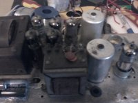
the volume and tone mains switch is one unit positioned right beside the PT and OT.,
the coupling capacitors are large red ceramic 10nf.
yes it is very minimal, not enough noise to worry about
Then logic says the 'buzz' is being picked up prior to C47?
As you do not need anything before C47 to use the amplifier section why not isolate the left connection (C47) from the 'radio' part and try feeding your audio/signal straight to it instead?
Was thinking maybe it would be good to have a tube as a pre-amp for a microphone before the the passive tone/volume controls. could maybe wire up the socket for a different tube if i cant get the noise down by removing the wiring from the un-used half of the tube,Then logic says the 'buzz' is being picked up prior to C47?
As you do not need anything before C47 to use the amplifier section why not isolate the left connection (C47) from the 'radio' part and try feeding your audio/signal straight to it instead?
Thanks for the reply. Do you Know if half of the ECH81 tube can be used alone? I thinking of disconnecting the power to the anode etc on the left hand side. not sure if the connected grids on each half are dependent for the tube to function properly.This is a very unusual schematics, regarding the »PU« operation. As any passive components that, at first glance (see your 2nd pic), appear to be in the audio path, are either high-ohmish resistors or low-pF capacitors, I suspect the ECH81 triode being also an oscillator then that is amplitude modulated by the PU input signal. The resulting RF signal is demodulated by the left diode in the first EBC41 and amplified by the radio's AF section, beginning with the triode in this tube. But I could as well be wrong, 'cause the rotary switches' function remain somewhat unclear to me.
My interpretation would explain the buzz issue, though, as a result of that many sources of RFI that we have nowadays.
Also interesting is why they've chosen the Noval ECH81 oscillator/frequency changer instead of a ECH42 from the set of Rimlock tubes.
Best regards!
also had a question about measuring speaker ohms, i know the ohms read slightly lower with a multimeter, i am trying to get an idea of what load the amp requires. i am unsure if the cross over coil and caps will give a false reading of the required load?
Last edited:
Was thinking maybe it would be good to have a tube as a pre-amp for a microphone before the the passive tone/volume controls. could maybe wire up the socket for a different tube if i cant get the noise down by removing the wiring from the un-used half of the tube,
I was trying to establish if it worked without the buzz as a line level amplifier.
If you actually need more gain for the mic, then you could use the triode section of the ECH81 for that. Just disconnect all the components to the left hand side on the schematic (from pins 1, 6 and 7). Then at the valve, join 1, 6 and 7 together and connect them to ground or to pin 3 (the cathode) which ever is the quietest.
At V4 (EBC41) better disconnect the wiring of the two diode sections (pins 5 and 6). Then join pins 5 and 6 to the cathode pin 7. They are / were the detector and AGC part of the original radio and not needed.
Ah yes, I have disconnected and tidied the diode and heptode wiring and i will try the tying the pins like you recommended.
have also removed the ac switch connections from the switch/potentiometer and relocated the all in one volume tone controls with shortened wiring away from the power transformer and added a mains fuse.
this has helped quite a bit. i think the best difference for noise so far has been re-routing the negative feed back at (R33 below the volume control)
the wiring for it and the + speaker in white was running along side the exposed underside of the ac transformer.
the buzzing is pretty minimal now and could probably be sorted by running the rest of the wiring more sensibly.
the only real noise now is a rustling sound that starts to come in when the valves are fully warm and is only noticeable above half volume and higher.
Attachments
- Home
- Amplifiers
- Tubes / Valves
- ech81 ecb41 el41 amplifier