had a read over the tube cad site jazbo8 recommended on the SRPP circuit. Understood some of this, from what I can see the OddWatt 8751 SRPP circuit is not very good to start with. the site does suggest some alteration to solve some of the problems with the SRPP stage but to be honest I don't want to start with something that already has major issues. Sad as I could get all the components for this circuit and I thought I was on my way.
I will have a read over the Baby Huey that aardvarkash10 suggested. On first look this looks more like the circuits I have started studying so may be a good choice. Need to see about sourcing the components for this one. Any one built one of these circuits and if so how good was it. What sort of power output would this deliver.
I will have a read over the Baby Huey that aardvarkash10 suggested. On first look this looks more like the circuits I have started studying so may be a good choice. Need to see about sourcing the components for this one. Any one built one of these circuits and if so how good was it. What sort of power output would this deliver.
I haven't built but there is a solid set of docs on it and several threads.
Expect around 12w to 15w although tbh the difference between those two points is almost unrecognisable irl.
Gingertube is the man to talk to. He's around here regularly
Expect around 12w to 15w although tbh the difference between those two points is almost unrecognisable irl.
Gingertube is the man to talk to. He's around here regularly
I have just read up on the Williamson Valve amp as a project idea. which is very well published on the following link
Valve Amps: Valve amp basics
But after spending some time reading and understanding this circuit I have now read poor reviews on this circuit due to the feedback elements.(all do this was on the original design)
I still need to read up on the Baby Hue already mentioned but wanted a bit more power than the possible 15 Watts this will provide.
So is the Williams really a bad design. Was designed also for the KT66 but the link above is for the KT88. I think 100 Watts is over the top so may need to redesign this to give less output.
I have also bought the book on valve amplifiers by jones morgan on Amazon. I'm hoping this will give me some inspiration for a project.
The end result is I would like a stereo system Class AB push pull output and driving towards 25 - 50 Watts.
My original circuit has been dismissed due to age of design and the OddBlock also had major design problems using the SRPP method.
Any suggestions and help much appreciated. I understand this is a tall order as there is a lot of designs on the web
Williamson needs good quality output transformers.
Under your new definition, Chris's AB2 as designed with this group's help or Pete's Engineer's Amp (the Red Board) with judicious modifications are the logical answer. I'm pretty sure thats the answer I gave in your other thread.
Under your new definition, Chris's AB2 as designed with this group's help or Pete's Engineer's Amp (the Red Board) with judicious modifications are the logical answer. I'm pretty sure thats the answer I gave in your other thread.
aardvarkash10 thanks for the reply. I did not see any reply on the other thread. To be honest this thread should be on another thread as it has very much changed.
The recommendation you have given look good. I have now found a couple of very good threads to read. i do like the look of both Chris AB2 and Peters red amp. from a quick look.
There is still some recommendations on the Williamson amp but i think for a first project this has a lot of issues that need tweaking so i will leave this one for now. Still got my book to read as well.
I think i will now read up on the two suggestions given and the book when it arrives and hopefully come up with a reasonable first project. Thanks all the help
What doesn't need tweaking?🙂 Kiebert already addressed all the problems with the Williamson design, the schematic was posted on the other thread.There is still some recommendations on the Williamson amp but i think for a first project this has a lot of issues that need tweaking so i will leave this one for now.
Hello All
i have done some reading since aadvarkash10 suggestions and have finally decided on a design to build.
i am going with Pete's Engineers Amp. I have already started reading the 100+ threads on here and his own web page. This looks a great design and well test by many people. proving to be a good starter project that can over time be adapted.
i have already ordered the PCB and now need to start resourcing the other components.
I will start a new thread on this as a UK engineers amp to show my progress and for help in the build. First hurdle will be getting the valves and transformers in the UK
i hope to learn a lot from this amp. i have got the book from Amazon that i ordered " valve amplifiers by jones morgan " but this starts straight in the deep end with Logarithms and Calculus (will need to relearn this)
i would like to thank all the people on this thread for helping me come to this decision. It has been a learning experience on its own from the original design i chose to the Engineers amp.
thank you
jaz,
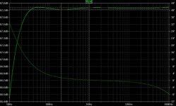
do you have any info about E80CF RIAA preamp into reality.
Sim results seem unreal well with any model 😕
Sri for OT.
do you have any info about E80CF RIAA preamp into reality.
Sim results seem unreal well with any model 😕
Sri for OT.
The 6BL8 is in the Ayumi library, but I don't have any exeprience with the tube. What kind of results are you getting, and which models have you tried?jaz,
do you have any info about E80CF RIAA preamp into reality.
Sim results seem unreal well with any model 😕
Sri for OT.
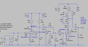
BTW
Just learned, Cin_triode is not nesesary if used Nakabayashi models in the simulation.
Without Cin_triode, with minor changes in RIAA eq, the results are still good.
Steve, please sorry for my off topics.
Moderators, you can delete my posts. Thanks.
Just learned, Cin_triode is not nesesary if used Nakabayashi models in the simulation.
Without Cin_triode, with minor changes in RIAA eq, the results are still good.
Steve, please sorry for my off topics.
Moderators, you can delete my posts. Thanks.
- Status
- Not open for further replies.
- Home
- Amplifiers
- Tubes / Valves
- ECF80 rating