Can some one please help me. I want to find the power rating for the ECF80 so i can check the bias is correct on an amp i an hoping to build.🙂
I got the ECF80 replacement from another site but can't remember where.
The data sheet you supplied is what i found and being very new at this, this is my week part.
What part tells me the gain and the power rating for the valve
The data sheet you supplied is what i found and being very new at this, this is my week part.
What part tells me the gain and the power rating for the valve
ive found some info on valve data sheet reading but still need to read more.
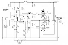
I was using this ECF80 to replace the ECF83 in the circuit attached. Its the phase inverter part so probable not a problem being a low signal valve.
I am new to this so still learning. sorry for not understanding this yet.😕
I also will be switch off soon after a night shift so will read reply later tonight. thanks
Attachments
Can some one please help me. I want to find the power rating for the ECF80 so i can check the bias is correct on an amp i an hoping to build.🙂
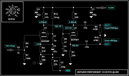
Maybe it will help this chart, the installation was made several copies and is useful for a final amplifier PP with very good performance.
ECF80 technical data here: ECF80 @ The National Valve Museum
Attachments
Last edited:
its also the voltage amp part, so yeah it's ratings are kinda critical.
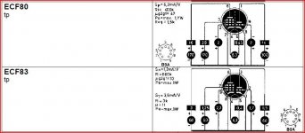
Heres a reasonable data sheet for it. If you want just the application data, its here. The PCF and ECF are operationally identical - just different heater voltages.
The ECF83 application data is here
There is an obvious difference in Ra between the two types for both sections which implies you may need to change load resistors to maintain performance. I haven't checked to see if they are pin compatible. I would imagine there is a capacitance difference between the two as well
If you change the cathode resistor of the pentode section I think it could function with a ECF80.
For me, the connection for the lower EL84 grid, is on the wrong side of the triode cathode resistance.
The gain of the amp is typical for old gear, today the output of most sources is much higher.Can do with much less input sensitivity, no need for a pentode input.
You could try this one for the east 🙂
Mona
Attachments
Thanks all for the replays. I will go over this tonight and see what is best. I still need to learn how to read the data sheets properly. I do know the pin out on both valves are the same but as some of you have said the plate and bias resistors may need changing.
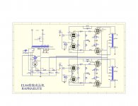
Ketje thanks for the schematic these look good. the second by raphaelite looks interesting but i will need to see if i can source the output transformer.
LAZAROIU did you do this schematic on a simulator and is so where can i find this as this would be very help full for learning
Ketje thanks for the schematic these look good. the second by raphaelite looks interesting but i will need to see if i can source the output transformer.
LAZAROIU did you do this schematic on a simulator and is so where can i find this as this would be very help full for learning
Where did you see that? The information I have seen says they are quite different. For example see ECF 80, Tube ECF80; Röhre ECF 80 ID2409, Triode-Pentode and ECF 83, Tube ECF83; Röhre ECF 83 ID3420, Triode-Pentode. This site is usually reliable.I do know the pin out on both valves are the same
The first link gives pins 8 9 1 for ECF80 triode cathode grid anode respectively.
The second link gives pins 1 2 3 for ECF83 triode cathode grid anode respectively.
i see what you mean. This i sa bid worrying, I got the EFC 80 pin out from the data sheet and compared it to the schematic from the following link.
EL84 Valve Amplifiers
So maybe the schematic is incorrect.
EL84 Valve Amplifiers
So maybe the schematic is incorrect.
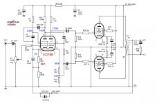
The nrs in the schematic are right for the ECF80 and they name it ECF83 😱i see what you mean. This i sa bid worrying, I got the EFC 80 pin out from the data sheet and compared it to the schematic from the following link.
EL84 Valve Amplifiers
So maybe the schematic is incorrect.
Since it was for converting to the 80, I only checked if it was ok, not if the 83 was different 🙁
Mona
Attachments
So from what you said and from the data sheet you posted the scematic actually is wired for the ECF80 already. (sorry not wanting to get to confused with all this)
If so then the ECF80 in this circuit hopefully should be fine
If so then the ECF80 in this circuit hopefully should be fine
Basically, as long as you get the pins rightly hooked up, it looks like it would work. Ketje's advice is great, and should be taken (re: resistor values).
However, just looking at the amplifier diagram, it seems to be full of capacitor values that might once have been 'cost effective' in an optimal sort of way, but which look small by today's “we need bass response” world. There's a lot of compensation to squash high frequency (supersonic!). Suggests that the original unadorned design was a whistler.
IF your ECF 80's are free or nearly so, then what the hey… just build it and see if it blows up. Everyone will want to hear your impression, should it work. If they're expensive, don't build it; replicate the original design if you like, or choose one with more liberal low-end responsive capacitor values.
GoatGuy
thanks for the reply goatguy. No i have not got the valves, i wanted to get a solid schematic and suppler for the valves and transformers before i bought anything. I also want to keep cost down for a first time valve amp project. So i don't really want to build a amp that is tinny and could erupt go bang.
I might have to rethink this and look at a different schematic.
Ketje schematic of the Raphaelite EL84 looks interesting. Anyone built this design. Will need to see if i can source the output transformer and cost all the part.
I might have to rethink this and look at a different schematic.
Ketje schematic of the Raphaelite EL84 looks interesting. Anyone built this design. Will need to see if i can source the output transformer and cost all the part.
If you are going to change approach as far as thinking about the Raphaelite, go one step further and build a Baby Huey.
The parts list is similar (except for the CCS stuff of course) and its a known performer with lots of support available right here including the designer, its predecessor's designer and many happy constructors.
The parts list is similar (except for the CCS stuff of course) and its a known performer with lots of support available right here including the designer, its predecessor's designer and many happy constructors.
-1, the BH is not a suitable project for a beginner IMO. It is in fact, quite an advanced design.If you are going to change approach as far as thinking about the Raphaelite, go one step further and build a Baby Huey.
Its advanced, but not difficult if you take your time. The CCS blocks are simple and can be individually tested, the rest is P2P and its very well documented. Sure, you won't throw it together in a couple of nights, but I don't think that is the OPs aim.
Lets agree its an option shall we?
Lets agree its an option shall we?
thanks every one for the help in making my mind up for a first project to begin with. I think with research the original scematic is not a good start. so i am going of looking for a new design.
aardvarkash10 thanks for the baby huey recomendation I will look over this tonight and see how good this is.
I am seriously looking at doing an OddWatt design which i know has been very well documented and reviewed on a few forums. I was first thinking about the oddblock KT120 until i saw the cost of the KT120 valves😱
So i am looking at building the oddBlock KT88 Series 1 (link below), I don't want to buy the kit as the fun is in sourcing and building from scratch (all be it well documented from scratch), and i can spread the cost out collecting the parts.
I can get the transformers imported from Edcor. These look cool transformers and are also very well rated as being a good build.
So any one got any thought between the OddBlock series 1 and the Baby Huey which has just been recommended. (need to read up on the baby Hue myself later)😀
OddWatt Audio 5751 SRPP / KT88 Push-Pull Monoblock Tube Amplifier Kits
You may want to read about the use of gratuitous SRPP circuit... plus a self-split output stage with a common CCS, why not...So i am looking at building the oddBlock <snip>
- Status
- Not open for further replies.
- Home
- Amplifiers
- Tubes / Valves
- ECF80 rating