Someone whispered in my ear that the two triode halves are not identical when it comes to heater vs. cathode? Is that right? More info?
Pers,
Some different data to the Philips:
I have a Sylvania data book that says the triode halfs are not quite identical, and in a cascode the triode on Pins 6, 7 & 8 should be the input/lower tube, and the triode on pins 1, 2 & 3 should be the upper tube. It has to do with different heater/cathode V ratings I believe.
I have always used the tube this way in a cascode, and have no experience using it the 'wrong" way around.
Regards, Allen (Vacuum State)
So if I understand it right, Mr. Wright, in my case I should have the triode 123 as the input device and the other half as CCS?
(PS: SY, the Phillips datasheet doesn't tell me the whole story DS)
(PS: SY, the Phillips datasheet doesn't tell me the whole story DS)
Last edited:
If the heater potential is under the cathode the heater will start to act as a cathode right, but when does this phenomena stop, at which voltage? Is 5 volts over the cathode enough, or 10, 20, 30V? Anybody who have some theory in this subject?
Pers,
Some different data to the Philips:
I have a Sylvania data book that says the triode halfs are not quite identical, and in a cascode the triode on Pins 6, 7 & 8 should be the input/lower tube, and the triode on pins 1, 2 & 3 should be the upper tube. It has to do with different heater/cathode V ratings I believe.
(Vacuum State)
That's actually consistent with the Philips datasheet. It rates the 1,2,3 section as Vhk = 150V max, with a 130V DC component, but only 50V for the 6,7,8 section. (page 2 and qualified in footnote 3).
If the heater potential is under the cathode the heater will start to act as a cathode right, but when does this phenomena stop, at which voltage? Is 5 volts over the cathode enough, or 10, 20, 30V? Anybody who have some theory in this subject?
And when it is above it will start to behave as an anode..................
While we're talking about this tube - pin 9 - the shield - do people just ground it typically?
Depends on the circuit. Sometimes, I just let it float if I'm worried about stray capacitance. It's not terribly critical for most audio applications.
If it's easy to do, just ground the Pin 9 shield to earth. I solder a short wire from the pin to the metal of the tube socket.
But if it means a long and messy wire to get to a ground, then leave it unconnected.
This shield is important in VHF RF gain stages, and **maybe** in an audio stage that shares a tube across two channels - but otherwise it's not so important IME.
Regards, Allen
But if it means a long and messy wire to get to a ground, then leave it unconnected.
This shield is important in VHF RF gain stages, and **maybe** in an audio stage that shares a tube across two channels - but otherwise it's not so important IME.
Regards, Allen
Hi to all,
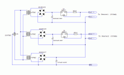
I made a simple schematic for elevating the heaters of two PCC88 tubes. The cathodes in my CF application have voltage about 70V above ground. I calculated heaters elevation about 30V above cathode voltage. The current sources are calculated for 300mA. Do you have any suggestions for improvement?
I made a simple schematic for elevating the heaters of two PCC88 tubes. The cathodes in my CF application have voltage about 70V above ground. I calculated heaters elevation about 30V above cathode voltage. The current sources are calculated for 300mA. Do you have any suggestions for improvement?
Attachments
I would suggest far more filtering on the heater elevation power supply.
Coming straight off a diode bridge will have some pretty severe spikes, and their HF content will go right through the heater/cathode capacitance and into the signal path.
Result: a 50/60Hz (or maybe 100/120hz) buzz you can't find and certainly can't fix.
As this heater lift power supply will have minimal/zero current drain, I'd put a big R after the diodes but before that big cap you have to gnd. I'd start with 10k, but try even higher,like even 100k.
Regards, Allen
I would suggest far more filtering on the heater elevation power supply.
Coming straight off a diode bridge will have some pretty severe spikes, and their HF content will go right through the heater/cathode capacitance and into the signal path.
Result: a 50/60Hz (or maybe 100/120hz) buzz you can't find and certainly can't fix.
As this heater lift power supply will have minimal/zero current drain, I'd put a big R after the diodes but before that big cap you have to gnd. I'd start with 10k, but try even higher,like even 100k.
Regards, Allen
Hi Allen,
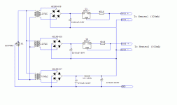
Thank you for your reply, i changed the circuit following your suggestion, but made C-R-C filter for even better ripple rejection. I now feed them with floating AC with no audible noise, so i thought that it wasn't critical.
Attachments
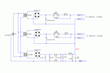
I finally made the following heater supply. The strange thing about it is that the last smoothing capacitor (marked as C2) has an impact in sound.
I have tried capacity values from 0.1μF to 100μF and all sound different.
Large values > 10μF do something like a HF sound rolloff, not dramatic but clearly audible. Smaller values favor HF and subjective audible resolution but i can describe the sound as thinner.
The GND is connected directly to the common star ground of HV power supply and this one is the only connection with the rest of preamp circuit.
Is anybody experienced similar behaviour?
Does it has to do with the fact i'm using seperate transformer for heater elevation or something else?
What do you think ?
Attachments
Because it SOUNDS better - that's why!
Regards, Allen (Vacuum State)
1. Is it true for all, or most tubes?
2. Is it better than floating DC filaments voltage?
3. When HT voltage is regulated and very quiet, is it better to elevate the filaments voltage by a resistors divider from the HT voltage, or to have a separate, well filtered supply for elevating the filaments?
1/ It's circuit dependant , not tube. It's most valuable in sensitive preamp circuits, although we often use it even on powertubes like EL34.
2/ Don't understand the quest. Is "what" better?
3/ I doubt if it makes any difference. I certainly have never bothered to make a seperate powersupply just for heater elevation. As all my B+ lines are seriously regulated, I only ever divide down from the B+.
Regards, Allen
2/ Don't understand the quest. Is "what" better?
3/ I doubt if it makes any difference. I certainly have never bothered to make a seperate powersupply just for heater elevation. As all my B+ lines are seriously regulated, I only ever divide down from the B+.
Regards, Allen
Thanks Allen,
About #2, you wrote earlier that the filaments are elevated from the cathodes because it sounds better. Does it sound better than floating filaments?
About #2, you wrote earlier that the filaments are elevated from the cathodes because it sounds better. Does it sound better than floating filaments?
- Status
- Not open for further replies.
- Home
- Amplifiers
- Tubes / Valves
- ECC88, warm up time


