The lm3886 gives it's best with gain of less than 3 , but oscillate bellow 10 . By applying as shown bellow you can run it as at high frequencies C1(to adjust) brings the gain to 10 . The tubes than give necessary gain. At start up , to keep the 3886 muted until the tubes are ready , you can use the cathode voltage to unmute .
To remind you a phenomena about 3886 , if the ac impedance at the input exceed 20k , the IC generates a shower noise .
I had similar problems with a tda7294.
I reduced its gain as I had a valve front end with gain and it just oscillated really badly. The oscillation from the tda got back into the valve through radiation and sent the valve nuts.
I found a patch was to put a 1nf across + and - inputs of the tda.
Another problem I noticed was a need to keep feedback resistor pat has short as possible to stop oscillation.
When I wanted a TDA7294 with a tube front end, I cheated and bought this: Tube 6N3 Preamp TDA7294 Power Amplifier Kit DIY 80W+80W | eBay
Interesting. How much did you have to change? Were there lots of counterfeit parts in the kit? Or were the supplied parts usable?
Is Chinese 6N3 tube the same as Russian 6N3P?
--
Is Chinese 6N3 tube the same as Russian 6N3P?
--
It worked as described. I simply added a 54VCT transformer, a case, and a pair of heatsinks. The one I got was preassembled. And yes, the 6N3 is = to 6N3P (which is better IMHO and the 5670 (which get HOT 🙂)
Hey guys!
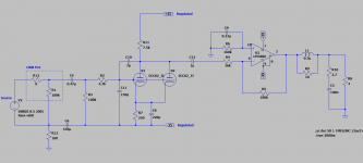
I've finished my project and I must say that I'm really satisfied with the result. Here is the final circuit and more info about my decisions, after one month of tinkering.
- Grid stopper of 4.7k with added capacitance(C10,C11) of around 240p(with miller's) witch gives fc of 140kHz. I've added and anode to grid cap to filter RF after the tube, not just before it.
- Plate load of 7.5k for 6.5mA current and 220r cathode resistor for -0.5V bias point. At this bias point and signal of 0.5Vpeak the THD is under 2%. I've also added cathode bypass cap to reduce the output impedance.
- R4 is chosen 36k witch is 10x tube stage output impedance of around 3.6k.
- The amp final gain is 36. 8 from the tube stage and 4.5 from the LM.
- R13, C6 are directly mounted on the POT to filter some noise entering the grid from the power center point common ground.
Has I said I'm really satisfied. The amp is dead quite. I can hear some hiss noise if I place my ear directly on the speaker. The sound is warm, rich with no audible distortion.