Hi Gents
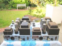
I have a pair of Pye HF25 tube amps due for refurbishing soon. I have a complete tube compliment for both except for one ECC33. I have searched locally but cannot find one for now. The HF25 manual states a 6SN7 tube as a suitable replacement and this I can get.
So common sense prevails in that in the absence of running one amp with an ECC33 and the other with a 6SN7 will not be an elegant solution. It would therefore be better to get a pair of 6SN7's in the meantime (one for each amp).
What do you think? Buy two 6SN7's or wait until another ECC33 turns up?
Thanks for your opinions!
bulgin
Attachments
ECC83 is a smaller Noval 9 pin base. The 6SL7 is near equivalent with an IO base. The 6SN7 is similar to ECC82.
I would use ECC83/12AX7WA. Plenty available on the Russian market.
12AX7 | eBay
I would use ECC83/12AX7WA. Plenty available on the Russian market.
12AX7 | eBay
I would use ECC83/12AX7WA.
It would be difficult to find a worse substitute. It's not even vaguely close.
It is suggested that ECC83's could be used as a substitute. The ECC83 is thew modern choice of all amplifier builders looking for decent quality. Excellent control of gain but the downside as we all know is the base. ECC32 is worth a look, IO base just a change in pin out. I would have thought that there are plenty of 6SN7 suppliers out there, I buy mine from the Soviet Union at a very keen price.It would be difficult to find a worse substitute. It's not even vaguely close.
Maybe SY knows something that no one else does?
I suggest you look at the data sheet of the ECc33 and compare it to that of a ECC83. For example, ECC83 has 6 times the rp of the ECC33. Does that sound like a good substitute? Also, ECC83 needs a NOVAL socket.
It is suggested that ECC83's could be used as a substitute.
Not by anyone competent, no. Six-to-ten times higher rp, triple the mu, totally different current for optimal operating point, totally different bias requirements. No special secret knowledge involved, just some very basic understanding.
The ECC33 has no real substitute but a 6SN7 is close enough to be used in this circuit without any modifications and if it recommended by PYE as an acceptable replacement there's no need to search further. Since the 6SN7 has lower Rp, Gm , and µ I would not use different types in the two amps and go for (good quality) 6SN7's in both of them. The problem with the ECC33 (and his relatives, ECC32,ECC35) is demand and scarcity which leads to outrageously high prices, especially the Mullard branded ones. (the designer of this tube). I tried both ECC33's and 6SN7's in my HF 25's and was unable to detect any noticeable difference in sound quality or performance. There are still plenty of good quality (N.O.S) 6SN7's on the market but the prices have a tendency to escalate recently and it's wise to stock a few. Of course, it has been already mentioned above that the ECC83's characteristics are so different that it can not be considered as a possible substitute for the ECC33, even with a socket replacement and circuits changes. (both things I would NEVER do on a Pye HF 25 !)
Last edited:
The ECC33 has no real substitute but a 6SN7 is close enough to be used in this circuit without any modifications and if it recommended by PYE as an acceptable replacement there's no need to search further. Since the 6SN7 has lower Rp, Gm , and µ I would not use different types in the two amps and go for (good quality) 6SN7's in both of them. The problem with the ECC33 (and his relatives, ECC32,ECC35) is demand and scarcity which leads to outrageously high prices, especially the Mullard branded ones. (the designer of this tube). I tried both ECC33's and 6SN7's in my HF 25's and was unable to detect any noticeable difference in sound quality or performance. There are still plenty of good quality (N.O.S) 6SN7's on the market but the prices have a tendency to escalate recently and it's wise to stock a few. Of course, it has been already mentioned above that the ECC83's characteristics are so different that it can not be considered as a possible substitute for the ECC33, even with a socket replacement and circuits changes. (both things I would NEVER do on a Pye HF 25 !)
Thank you, thank you Tubologic. Your post reflects exactly what I wanted to know. I would never change anything on these amplifiers and my plans for refurbishing are far advanced. New rubber feet have been fitted, custom matched light blue paint is here, grey etch primer and black gloss duco for the trafo covers in stock and next week I should have new darkblue aluminium legend plates.
The black type on top and on the front face laserprinted on waterslide film will also be here next week.
I will take progress pics and post them in this thread.
Regds
bulgin
Last edited:
Just to chime in,
I have replied to Bulgin on a local forum. As said, 'similar', depending on how far out the circuit can accept. I find enough difference in operating point e.g. bias between ECC33 and 6SN7 for the same circuit values, that e.g. as driver for power stages operation could be compromised - thus depending. If that is what PYE suggests however, then fine - if the increase in distortion is disregraded/acceptable. (I did not specifically examine the HF25 schematic.)
@ SY,
Correct (as usual!). Folks must just be careful to compare tube characteristics under the same conditions. General specs for tubes are often at quite higher Ia than e.g. common in voltage amplifiers. Low-Ia equivalent data is not often found for comparison. Those may be better/worse than the original. But to concur, there is no ideal way out in the case of ECC33. (If my own amplifier, I would at least restore NFB to the original value. Decrease in nett gain should be acceptable.)
I think he knows that ECC83 and ECC33 might look similar - but only if you cover up the left side of the 8 so it looks like a 3. Apart from that the only similarities are that they are both dual triodes and both can run from a 6.3V heater supply.JonSnell Electronic said:Maybe SY knows something that no one else does?
In my humble opinion, the sound of ECC33 is much more delicate than the sound of 6SN7. Additionally, there is a big gain. But the price is dramatically high.
Comparing the sound ECC33 Mulard NOS, with 6SN7GTB of Tung-Sol , new production.
Best regards from Bulgaria
Comparing the sound ECC33 Mulard NOS, with 6SN7GTB of Tung-Sol , new production.
Best regards from Bulgaria
The sound of a tube is a debatable topic, as well as if the added "delicacy" really worth 350$ (and more) for a small signal dual triode. The ECC33 has a higher amplification factor (35 vs 20 for the 6SN7) but in an amplifier with global NFB the gain difference will be small (if any). The ECC33 is indeed a wonderful tube but even in Europe they are very scarce and outrageously expensive. And strangely enough, the ECC33 was primarily intended for use in flip-flops and computer circuits, not really an audio tube...
The ECC83 is thew modern choice of all amplifier builders looking for decent quality. Excellent control of gain ....
Jon,
yes .... not to hammer any more nails into the coffin, but you provide the nails! It is really a sweeping statement to say "all amplifier builders looking for a decent quality."
To be direct: That is unfair and patently untrue flag waving for the ECC83. It has its place but is also one of the more 'used-in-unsuitable-applications' tubes. I will not amplify before we go OT. Let me just modestly state, for the record only, that those of us who 'grew up' with tubes like myself is getting scarcer. "All amplifier builders ..."? Sorry - not in my time, mate! 🙂 🙂
"Modern choice"?? Let's rather leave it at that and how uninformed such choices often can be these days ....
Maybe SY knows something that no one else does?
"...NO one else"?? Really? Another sweeping statement - no further comment ....
Regarding audibility and 'gain-noticability':
Not in an amplifier with reasonable NFB. But that is not the point. I have since kindly been furnished with a schematic of the HF25. At first glace it would seem that the loop gain with 2 x 6SN7 instead of 2 x ECC33 is halved. (In this particualr circuit the change in electronic working voltages does not seem to matter.) Thus double the distortion, which is what I was referring to. The output balance of the phase inverter (V2) would also be slightly affected; easy to correct. Again not to be pedantic; that is simply the situation and it might be audible under certain conditions but not in general.
I can understand the need to keep it unaltered; if it was mine I would at least change feedback resistors to restore original NFB factor, in which case it would be "more" the original HF25.
Jon,
Not in an amplifier with reasonable NFB. But that is not the point. I have since kindly been furnished with a schematic of the HF25. At first glace it would seem that the loop gain with 2 x 6SN7 instead of 2 x ECC33 is halved. (In this particualr circuit the change in electronic working voltages does not seem to matter.) Thus double the distortion, which is what I was referring to. The output balance of the phase inverter (V2) would also be slightly affected; easy to correct. Again not to be pedantic; that is simply the situation and it might be audible under certain conditions but not in general.
I can understand the need to keep it unaltered; if it was mine I would at least change feedback resistors to restore original NFB factor, in which case it would be "more" the original HF25.
To avoid any more confusion I just wanted to point out that the 1st stage of the HF25 is not a ECC33 but an ECC35 (very close to a 6SL7) and there was never any intention of the O.P to substitute this tube with a 6SN7, nor do I recommended this substitution.(though a 6SL7 can be used in this postition). Also, replacing the ECC33 may change the open loop gain of the amp but will have absolutely no effect on the global NFB factor which is fixed and independant of the active element (the tube), thus there's no need to "restore the original NFB factor".If you want to compensate any (supposed) gain loss of the amp you'll need to decrease global NFB which will actually INCREASE distorsion in the same ratio. All this is purely academic as the circuit is not so critical and the amp works equally well with an ECC33 or 6SN7 in the 2nd stage. I have both a PF91 and HF25 and tried these substitutions many years ago without being able to notice any changes in sound, gain or (audible) performance. I didn't measured the before/after distorsion characteristics,there must be very likely a difference (in better or worse) but so small I would consider it insignificant for all pratical purposes. Again, any circuit could be optimized but I would not recommend changing any parts values in the HF25 without a very careful circuit analysis and comparative lab measurements on the actual unit, which are (I think) beyond the O.P abilities.
Last edited:
Okay folks,
My bad - the schematic I received did not state tube numbers or component values. As the tube change is then only in the ltp phase inverter, the loop gain diminishes to some 80% only of the original. As said earlier my original concern was (glibly) equating ECC33 and 6SN7 without knowing the circuit, while one finds different operating points for the two tubes in the same circuit (from the datasheets of both).
Not desiring to perpetuate this, but the amount of NFB is determined by the open loop gain. I fail to see how this is not affected by the 'internal' tube gains. The final amplifier gain with NFB is fixed by the feedback resistor ratio, not the amount of the feedback. On my diagram: (R13+R4)/R4 (neglecting R5 which is shunted by the R24-R25 network, values unknown to me but probably low). Thus, double the open loop (internal) gain and the feedback factor doubles (20dB becomes 26dB etc.) with the same resistor values R4 and R13. Perhaps semantics or something?
Again, explained to the OP which I hope he accepts. I will stand down.
My bad - the schematic I received did not state tube numbers or component values. As the tube change is then only in the ltp phase inverter, the loop gain diminishes to some 80% only of the original. As said earlier my original concern was (glibly) equating ECC33 and 6SN7 without knowing the circuit, while one finds different operating points for the two tubes in the same circuit (from the datasheets of both).
Also, replacing the ECC33 may change the open loop gain of the amp but will have absolutely no effect on the global NFB factor which is fixed and independant of the active element (the tube)
Not desiring to perpetuate this, but the amount of NFB is determined by the open loop gain. I fail to see how this is not affected by the 'internal' tube gains. The final amplifier gain with NFB is fixed by the feedback resistor ratio, not the amount of the feedback. On my diagram: (R13+R4)/R4 (neglecting R5 which is shunted by the R24-R25 network, values unknown to me but probably low). Thus, double the open loop (internal) gain and the feedback factor doubles (20dB becomes 26dB etc.) with the same resistor values R4 and R13. Perhaps semantics or something?
Again, explained to the OP which I hope he accepts. I will stand down.
Okay folks
Not desiring to perpetuate this, but the amount of NFB is determined by the open loop gain.
Not so. The amount of feedback (or feedback factor, usually designed by the term Beta) has nothing to do with the open loop gain of the amp. It only quantify how much of the output signal is applied back to the input and is only determined by the feedback network around the amplifier. It's a ratio most usually expressed in dB. For instance, if your amp has 30 dB of global NFB and you substitute the tubes with another type the NFB still remains 30 dB.
I fail to see how this is not affected by the 'internal' tube gains. The final amplifier gain with NFB is fixed by the feedback resistor ratio, not the amount of the feedback.
The feedback resistor ratio IS the amount of feedback !
On my diagram: (R13+R4)/R4 (neglecting R5 which is shunted by the R24-R25 network, values unknown to me but probably low).
Correct, and no tube parameters involved in your analysis.
Thus, double the open loop (internal) gain and the feedback factor doubles (20dB becomes 26dB etc.) with the same resistor values R4 and R13.
No, the feedback factor (B) remains the same. (see above) The closed loop gain will drop slightly.
Tube parameters will definitely influence the open loop gain of the amp but if this open loop gain is much greater than unity (which is nearly allways the case in audio amplifiers) the closed loop gain becomes 1/B and is only determined by the feedback network, NOT the active element. (tube ,opamp,etc...), otherwise the gain of your amp (or preamp) would constantly change during the aging of the tubes and one of the (good) characteristics of negative feedback is just to STABILIZE gain.
Perhaps semantics or something?
Probably so. It's only basic feedback theory but the correct terms and definitions must be used.
Last edited:
The feedback resistor ratio IS the amount of feedback !
I believe you guys are saying the same thing but apparently there are differences in technical English usage between various countries and/or individuals.
In the US, or at least where I was educated, the "amount" of FB would be the amount (just as the word states) being fed back, measured in volts or amps. The FB factor would be a ratio, meaning a unitless number and usually expressed in dB.
Correct. The feedback resistors determine the feedback fraction, B. The 'amount of feedback' is 1+AB and is therefore infulenced by the open loop gain, A. But if A is large, only B really matters.I believe you guys are saying the same thing but apparently there are differences in technical English usage between various countries and/or individuals.
This is what Bob Cordell writes in his book "Designing Audio Power Amplifiers":
The basic amplifier has a forward gain Aol. This is called the
open-loop gain because it is the gain that the overall amplifier would
have from input to output if there were no negative feedback. A
portion of the output is fed back to the input with a negative
polarity. The fraction governing how much of the output is fed back is
referred to as beta(ß). The negative feedback loop gain is the product
of Aol and ß. The overall gain of the closed-loop amplifier is called
the closed-loop gain and is designated as Acl. The action of the
negative feedback opposes the input signal and makes the closed-loop
gain smaller than the open-loop gain, often by a large factor.
The output of the subtractor at the input of the amplifier is called the
error signal. It is the difference between the input signal vin and
the divided-down replica of the output signal. The error signal, when
multiplied by the open-loop gain of the amplifier, becomes the output
signal. As the gain Aol becomes large, it can be seen that the error
signal will necessarily become small, meaning that the output signal
will become close to the value vin/ß. If Aol is very large and ß is
0.05, it is easy to see that the closed-loop gain Acl will approach
20. The important thing to notice here is that the closed-loop gain in
this case has been determined by ß and not by the open-loop gain Aol.
Since ß is usually set by passive components like resistors, the
closed-loop gain has been stabilized by the use of negative feedback.
Because distortion can often be viewed as a signal-dependent
variation in amplifier gain, it can be seen that the application of
negative feedback also reduces distortion.
- Status
- Not open for further replies.
- Home
- Amplifiers
- Tubes / Valves
- ECC33 vs 6SN7 - Implications I should know?