Hello,
Reading Igor Popovich`s books make me dream of putting together EC8010, AD1 and 845 tubes. This is what came out.
Anyone interested in building this baby?

The chassis was done with a power drill, a file and a saw, costed me 20eur, look at the beauty of Lundahl iron, more beautiful than many hi end butt ugly cans, at least in the eyes of the owner.


Reading Igor Popovich`s books make me dream of putting together EC8010, AD1 and 845 tubes. This is what came out.
Anyone interested in building this baby?
The chassis was done with a power drill, a file and a saw, costed me 20eur, look at the beauty of Lundahl iron, more beautiful than many hi end butt ugly cans, at least in the eyes of the owner.
Last edited:

Nowadays AD1 is rare as a hen's teeth ... and expensive as Koh-i-Noor. Using its as "simple" driver IMHO waste of money and waste of potential.
There is a new production from Emission Labs, if you study my schematic, you will see that i use their variant of AD1. I agree with you old AD1 is rare and expensive, and very fragile in my humble opinion.
Some performance measurements without NFB:
Output power: at least 10Vrms into 8ohm undistorted sine wave.
-3dB bandwidth: 10Hz-26KHz at 1W into 8ohm.
THD: 0.52% at 1W into 8ohm
Noise: 0.8mV or -70dB referenced to 1W.
Output resistance: 1.76ohm
Damping factor: 4.54
With -6dB feedback noise and distortion halves, typical.
About sound: it has the transparency of EC8010, the tenderness and micro dynamics of AD1 and the slam of 845, a very rare combination indeed.
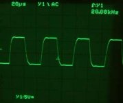
10KHz square wave:

THD:

Output power: at least 10Vrms into 8ohm undistorted sine wave.
-3dB bandwidth: 10Hz-26KHz at 1W into 8ohm.
THD: 0.52% at 1W into 8ohm
Noise: 0.8mV or -70dB referenced to 1W.
Output resistance: 1.76ohm
Damping factor: 4.54
With -6dB feedback noise and distortion halves, typical.
About sound: it has the transparency of EC8010, the tenderness and micro dynamics of AD1 and the slam of 845, a very rare combination indeed.
10KHz square wave:
THD:
Dear Kay, of course it is not crossover distortion.
It is typical, banal, RC low pass filter square wave response. I have at least 3 in this amp( grid stopper resistor and input capacitance on each tube). The added effect can give such square wave response. It is almost perfect response, for my standards, at least.
Best regards!
It is typical, banal, RC low pass filter square wave response. I have at least 3 in this amp( grid stopper resistor and input capacitance on each tube). The added effect can give such square wave response. It is almost perfect response, for my standards, at least.
Best regards!
Interesting amp, you can see the large 2H component as a bump in the square wave. I'd be interested in seeing the 100hz & 20khz squarewave response.
The only thing I'd add are two 1m resistors from the wiper of the bias pot to each end of the pot to prevent a no bias situation. I also see no fuse on the HT which is something I always do, by that I mean just before the diodes/doubler. There's a lot of expensive iron there a fuse might just them in an over current situation.
The only thing I'd add are two 1m resistors from the wiper of the bias pot to each end of the pot to prevent a no bias situation. I also see no fuse on the HT which is something I always do, by that I mean just before the diodes/doubler. There's a lot of expensive iron there a fuse might just them in an over current situation.
You did not replied, is 20kHz and 100Hz response to your likening?Interesting amp, you can see the large 2H component as a bump in the square wave. I'd be interested in seeing the 100hz & 20khz squarewave response.
The only thing I'd add are two 1m resistors from the wiper of the bias pot to each end of the pot to prevent a no bias situation. I also see no fuse on the HT which is something I always do, by that I mean just before the diodes/doubler. There's a lot of expensive iron there a fuse might just them in an over current situation.
Slew Rate limitation ... due to the AD1's plate choke ?The output signal appears to show crossover distortion. But you're SE. Why?
Best regards!
I think I understand what Stereophile readers look for from the measurements: a sense of any technical flaws inherent in the design. For example, you see some products that have a very difficult time reproducing a semblance of a square wave. You would tend to think that an amplifier should do that credibly. If it does not, then you begin to question the fundamental design.10kHz square wave with -6dB feedback, simple resistor without compensation cap
That hump it is not just an tendency to oscillation?
Some rainy days here, had time to make more measurements, i know that you like them.
First i think that all of you are wondering where the resonant peak of LC coupling is.
It`s at 15Hz +6db level, rapidly decreasing above and bellow 15Hz, with with only +0.5db at 40Hz and 0db at 100Hz.
For input stage i get 1Hz-162khz bandwidth and 0.3% THD, measured with the probe at EC8010 anode for 1W into 8Ohm at amplifier output.

For input stage and driver stage together i get 10hz-146khz bandwidth and 0.13% THD measured with the probe at AD1 anode for 1W into 8Ohm at amplifier output.

Interesting to see is the square wave response at 20khz, light blue is input stage anode, red is driver stage anode, dark blue is 845 grid, and yellow is the output into 8ohm.

First i think that all of you are wondering where the resonant peak of LC coupling is.
It`s at 15Hz +6db level, rapidly decreasing above and bellow 15Hz, with with only +0.5db at 40Hz and 0db at 100Hz.
For input stage i get 1Hz-162khz bandwidth and 0.3% THD, measured with the probe at EC8010 anode for 1W into 8Ohm at amplifier output.
For input stage and driver stage together i get 10hz-146khz bandwidth and 0.13% THD measured with the probe at AD1 anode for 1W into 8Ohm at amplifier output.
Interesting to see is the square wave response at 20khz, light blue is input stage anode, red is driver stage anode, dark blue is 845 grid, and yellow is the output into 8ohm.
Without any negative feedback . . .
That is a really odd square wave shape for a single ended output transformer.
Check the wiring of the primary, and check the wiring of the secondary.
So many different combinations; pick the right one.
The air gap is for 60mA, but is 60mA supposed to be OK, if all the primary windings are in series?
(60mA x total primary turns)
What is the DC quiescent current of the 845?
60mV at tp1 (1 Ohm) = 60mA
The slew rates of the input tube plate, driver tube plate, and output tube grid seem OK.
So, the problem is in the 845 plate circuit, and output transformer.
Just my opinion
Last edited:
Plain vanilla, that is the output transformer.
I do not see why you find it odd, any SE output stage breake into an waveform like that, maybe not at 20kHz.
I am pretty sure that even ISO have an waveform like this at 25khz? 30khz? Who knows, you do not see measurements like this on diyaudio.
Iddle current is 55mA, 55mV on 1 ohm resistor.
Transformer is wired 100% correctly, I checked before I installed it, by inputting 5V and I got 136mV on output, exactly the supposed TR.


IMHO 55mA is very low for 845 (yes, I know that this Lundhal OPT primary current is limited, and output power too -13W-), so THD higher than expected.
If you choose another operating point (higher B++, higher anode current), the distortion will decreasing (and power increasing).
The other "bottleneck" is the LF bump (due to the AD1 output impedance, choke impedance, coupling capacitor value).
If it's present, must to increase cathode decoupling.

If you choose another operating point (higher B++, higher anode current), the distortion will decreasing (and power increasing).
The other "bottleneck" is the LF bump (due to the AD1 output impedance, choke impedance, coupling capacitor value).
If it's present, must to increase cathode decoupling.
It's not odd but it is disappointing. Not a surprise tough, some Lundahls are ok and others are poor. In this respect they are inconsistent across the catalogue. The reason, I think, is that they use a fixed winding scheme for everything in each transformer "family". So that design will be good for some applications and bad for others. In my opinion that square wave is only acceptable for a cheap transformer although there are some cheap transformers that are surprisingly good in this respect.I do not see why you find it odd, any SE output stage breake into an waveform like that, maybe not at 20kHz.
I am pretty sure that even ISO have an waveform like this at 25khz? 30khz? Who knows, you do not see measurements like this on diyaudio.
Below you can see the 20KHz square wave of the Tango U-808 which belonged to the basic line of their OTPs.....
Attachments
I guess if you use a 211 tube, u=12, Gm about 3000uMhos, and about 4000 Ohms plate impedance or more at only 55mA quiescent Ip . . .
And then you combine it with a transformer that is not well matched for 211 service, you get what you get.
And, you got it.
Do not increase the B+ voltage; instead, reduce the negative bias voltage until you get 60mA plate current.
(look at the curves at various bias volts and plate volts; check where the slope is curving, not straight. rp is much larger at the curve than at the straight line)
The output transformer is specified at 60mA when set to 11k primary, Right?
I asked you to check that.
Take Lundahl at their word; if it does not meet specs, send it back for a refund ($$$).
Then purchase a less elegant but more capable E-I transformer with a single Air Gap.
I am just thinking out loud.
- Home
- Amplifiers
- Tubes / Valves
- EC8010 & AD1 & 845