The 75R resistor is for terminating the input (75R for consumer sp/dif). Coax cable has to be 75R impedance too, that's defined by sp/dif standard. The capacitor is for blocking DC, isolation. Resistor values are depended on what source and destination the signal has, defined in datasheets, to match impedance and avoid reflections, maintaining signal integrity.
Because the dac is slaved to the clock derived from sp/dif signal, it's very well possible to hear differences when quality of the sp/dif signal varies (jitter). When using USB board, quality of that board's clock will determine sp/dif quality, the same as it will influence SQ when using i2s.
Because the dac is slaved to the clock derived from sp/dif signal, it's very well possible to hear differences when quality of the sp/dif signal varies (jitter). When using USB board, quality of that board's clock will determine sp/dif quality, the same as it will influence SQ when using i2s.
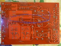
Next the bad grounding needs to be solved. This dac version 1 has the (analog) ground plane of the dacs connected directly to the (digital) ground of the AK4113 and MCU, which isn't according to datasheet recommendations. When the digital +5V of the dac has been transferred to the other group, this bad grounding will lead to distortion in left channel of the dac. To avoid this, I separated AK4113/MCU ground with dac ground plane, and connected both grounds at the supply side by connecting the - of the capacitors of both groups with each other (blue wire). You can see the rectangular ground plane of the AK4113 at the top of the picture, being cut from the bigger ground plane of the dacs.
The green (ground) wires are the main ground/return connections of the regulators, as a result of the regulator grounding mod I described earlier.
Nino
Hi Nino,
I did this ground modification per your directions. I have to say that this is another killer modification. My dac is much more quieter at higher volume levels now.
My amplifier has a vu-metre display which was displaying one channel at higher levels (due to some interference) albeit channels having same listening levels before modification. This strange defect that I couldn't understand has gone now.
Thank you again for such valuable contributions to threat.
Regards.
The 75R resistor is for terminating the input (75R for consumer sp/dif). Coax cable has to be 75R impedance too, that's defined by sp/dif standard. The capacitor is for blocking DC, isolation. Resistor values are depended on what source and destination the signal has, defined in datasheets, to match impedance and avoid reflections, maintaining signal integrity.
Because the dac is slaved to the clock derived from sp/dif signal, it's very well possible to hear differences when quality of the sp/dif signal varies (jitter). When using USB board, quality of that board's clock will determine sp/dif quality, the same as it will influence SQ when using i2s.
Surely USB board quality makes the difference, but i experienced that using a small cap in series with the connection cable from USB board to DAC input makes a great difference in frequencies reproduced by the DAC, just like an high pass filter, i don't know why. Maybe it acts on SPDIF signal quality?
There is an idea of a two-stage power regulation DAC. lt1963, followed by lt1763. Lt1963 put on 7-8 volt output voltage. And up to 5 volts to stabilize lt1763. What do you think?
terranigma: Thanks for sharing your findings. I'm glad you like the mod and it solved the channel unbalance as well🙂
730user: You can try any regulator you like, but for +5V analog the impedance of the regulator is most important. So it must be able to deliver current fast, while maintaining voltage. Regulator noise or ripple should (theoretically) be cancelled out by output stage, due to balanced outputs of the dac: the same ripple or noise will be present in both + and - outputs. What are your considerations to choose the two regs?
I doubt if using a pre-regulator will have benefits regarding impedance, but you can always give it a try and listen 😉
Nino
Thank you very much! Made both mods, board works! But tracks cut differently.transferring digital +5V
Attachments
Hi magicwolf,
Congratulations! Hope you like the results, SQ improved in your setup?
As a last step in this digital +5V transfer mod, I removed the inductors in the supply lines and replaced them with wire bridges. This resulted in much better highs. I removed them before, but replaced again because the high tones weren't clean, it didn't sound right, but now I did the TVDD mod and this transfer of digital +5V, I finally like the sound better without the inductors. It has a rather big impact on the sound, you can try it yourself.
Regards
Nino
Unfortunately, I made at the same time some mods therefore I can't precisely tell as each mod separately affected a sound. Earlier I tried to do each mod separately as you advised, but it very long 😉.Congratulations! Hope you like the results, SQ improved in your setup?
IMHO, mod for a digital supply of chips DAC doesn't change to a sound. Ground mod for chips DAC improves mid frequencies.
Thanks! I will try.As a last step in this digital +5V transfer mod, I removed the inductors in the supply lines and replaced them with wire bridges.
Removing inductors
I don't want to comment your results regarding SQ after removing them, but scientifically, removing them without checking the things with an RF oscilloscope is not wise, sorry.
respect,
robert
Removing inductors (which counts only for radio frequency, keeping the power-supply lines free of radio garbage) it's a mistake, Nino. In all expensive professional recording/studio equipment you will find many more anti EMF and anti-radio measures. Those inductors are thick bare wires, 3-4 cm long, wounded around a ferrite, that could not affect the sound except you remove them 🙂Hi magicwolf,
Congratulations! Hope you like the results, SQ improved in your setup?
As a last step in this digital +5V transfer mod, I removed the inductors in the supply lines and replaced them with wire bridges. This resulted in much better highs. I removed them before, but replaced again because the high tones weren't clean, it didn't sound right, but now I did the TVDD mod and this transfer of digital +5V, I finally like the sound better without the inductors. It has a rather big impact on the sound, you can try it yourself.
Regards
Nino
I don't want to comment your results regarding SQ after removing them, but scientifically, removing them without checking the things with an RF oscilloscope is not wise, sorry.
respect,
robert
Hi Robert
Thanks for your comments. In this case I have another opinion, maybe you can follow me.
The lines in which the ferrites are positioned are digital +5V for the DACs. The DACs are operating at high frequencies, so the load varies quickly accordingly. For cleaning the supply lines of RF/HF noise, the beads are fine, but what about fast currents needed by the load? Their flow will be counteracted too by the ferrite.
You could leave the bead in place and provide for a better decoupling close to the chip as an alternative. But then I guess you'll need a much bigger decoupling cap then the recommended 10u on datasheet.
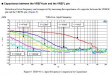
I'd also like to refer to a document by AKM, I uploaded here. On page 4 titled '10 steps to better audio' , step 2, their advice is not to place inductors in supply lines.
In the past I did other modifications to this DAC and removed them later, this could also be the case with this removal of the beads. But for now I like the resulting sound better.
Regards
Nino
Thanks for your comments. In this case I have another opinion, maybe you can follow me.
The lines in which the ferrites are positioned are digital +5V for the DACs. The DACs are operating at high frequencies, so the load varies quickly accordingly. For cleaning the supply lines of RF/HF noise, the beads are fine, but what about fast currents needed by the load? Their flow will be counteracted too by the ferrite.
You could leave the bead in place and provide for a better decoupling close to the chip as an alternative. But then I guess you'll need a much bigger decoupling cap then the recommended 10u on datasheet.
I'd also like to refer to a document by AKM, I uploaded here. On page 4 titled '10 steps to better audio' , step 2, their advice is not to place inductors in supply lines.
In the past I did other modifications to this DAC and removed them later, this could also be the case with this removal of the beads. But for now I like the resulting sound better.
Regards
Nino
Did you think is more important capacitor size or capacitor speed for digital ak4399 power supply?Hi Robert
You could leave the bead in place and provide for a better decoupling close to the chip as an alternative. But then I guess you'll need a much bigger decoupling cap then the recommended 10u on datasheet.
The lines in which the ferrites are positioned are digital +5V for the DACs. The DACs are operating at high frequencies, so the load varies quickly accordingly. For cleaning the supply lines of RF/HF noise, the beads are fine, but what about fast currents needed by the load? Their flow will be counteracted too by the ferrite.
Exactly. This blocking of HF is part of the intended operation of chokes/beads in digital supplies. They keep current loops at the local decoupling cap, and therefore keep earths clean and RFI low. Think of the total path the current has to flow through. This path will act as an antenna, and needs to be kept as small as possible
At audio frequencies where there is a dynamic load then chokes are less good.
Inductors
easy boys, just fallow our golden concept; LML
Listen, Modify, Listen!
in this case:
Listen, remove, Listen!
btw, shouldn't the case, box, enclosure, eat up all the shitty flies on the air?
easy boys, just fallow our golden concept; LML
Listen, Modify, Listen!
in this case:
Listen, remove, Listen!
btw, shouldn't the case, box, enclosure, eat up all the shitty flies on the air?
Last edited:
Spartacus: Thanks for explaining, this makes sense to me 🙂. I'll go further experimenting with the local decoupling then, and restore the beads.
Paolo: Difficult, I think besides speed, capacity is also important to have sufficient local energy storage.
Nino
Paolo: Difficult, I think besides speed, capacity is also important to have sufficient local energy storage.
Nino
Last edited:
I think speed ... 10uf are a big capacityDifficult, I think besides speed, capacity is also important to have sufficient local energy storage.
DVDD (fs = 192kHz) typical is 46mA max 70mA...
change capacitor don't change performance in this area
Nino, you are very welcome! Have enjoyed reading yours and others' experiences with this DAC. Have thought about buying one myself, but I see there DACs with the new AKM chips coming out.
- Status
- Not open for further replies.
- Home
- Source & Line
- Digital Line Level
- ebay:Weiliang Dual X2 AK4399 DAC with LCD