Oops, Oscons are on the onboard clock, not the dac, my bad...
They are smaller, 6.3V ones as I recall.
My DAC digital side is only a cerafine, bypassed by a tiny smd capacitor.
They are smaller, 6.3V ones as I recall.
My DAC digital side is only a cerafine, bypassed by a tiny smd capacitor.
Hello, NinoSimona !
I would like to ask you to give very detailed information on replacing Lt1085 per MC7805ACT. If it is possible, with a photo of the board. Not quite clear about the resistors. They simply need to do to remove or jumper?
Please give more information about times of nominal electrolytes you put some stabilizers.
Thank you in advance. 🙂
Last edited:
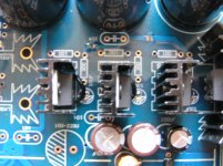
Thank you very much! How I understood it is possible to change condensers in 7,6,4 areas only for the sake of esthetic interest?!Magicwolf: I checked your pictures.
magicwolf: If you want to use MC7805ACT, 100u capacitor in area 4 will do. Pick your favorite brand, I use Elna Silmic II for the 2 analog regulators (your option 2).
area 7: Aren't those blue caps 47u? Anyway, just a matter of taste IMO, these 4 caps are important though. Experiment.
area 6: digital lines, no need for audio grade caps. Read this thread, I posted some mods regarding psu of AK4113. The capacitor right after the LT1085-3.3 I replaced by a bigger 220u, if I remember.
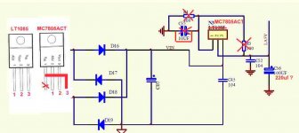
730user: Do you have the schematic? Just look at it, it's not that hard. You can do it!😉 [for version 1 schematic] Remove the two resistors (R3+R4) and the capacitor (C35). In place of the capacitor a bridge, shorting it. This way pin 1 is connected to ground, pin 2 to out, pin 3 to in. Now modify the MC7805ACT as in the picture and remove the 4th pin inside the heat sink, and solder the new regulator. If you have some patience, I'll post some pictures later.
area 7: Aren't those blue caps 47u? Anyway, just a matter of taste IMO, these 4 caps are important though. Experiment.
area 6: digital lines, no need for audio grade caps. Read this thread, I posted some mods regarding psu of AK4113. The capacitor right after the LT1085-3.3 I replaced by a bigger 220u, if I remember.
730user: Do you have the schematic? Just look at it, it's not that hard. You can do it!😉 [for version 1 schematic] Remove the two resistors (R3+R4) and the capacitor (C35). In place of the capacitor a bridge, shorting it. This way pin 1 is connected to ground, pin 2 to out, pin 3 to in. Now modify the MC7805ACT as in the picture and remove the 4th pin inside the heat sink, and solder the new regulator. If you have some patience, I'll post some pictures later.
Last edited:
I am not foolish, simply lazy. 🙂
So right?
Can С36 be increased to 220uf or anymore?
What values of capacitor in the feed of OPAMP did you put?
So right?
Can С36 be increased to 220uf or anymore?
What values of capacitor in the feed of OPAMP did you put?
Attachments
Last edited:
Aren't those blue caps 47u?10uF. Area 4 - 10uF. On a board it is written 100uf - caps 10uF.
I read your notes and made new the table of replacement of caps:
Caps - My Photo Gallery
Big to you thanks! I almost understood everything.
why 12v to opAmp?
We change the 5v reg to fixed MC7805 (10uV niose) Ok.
isn't it more sexy with 15v (MC7815 and MC 7915) or may be even 18? just fot the opAmps.
coments, thanx.
We change the 5v reg to fixed MC7805 (10uV niose) Ok.
isn't it more sexy with 15v (MC7815 and MC 7915) or may be even 18? just fot the opAmps.
coments, thanx.
The regulator doesn't need a big output cap, just try yourself. With a too big capacitor the regulator can oscillate, which is not good... I have soldered a 1u Wima polyester cap between input and ground of the regulator, on the backside of the PCB, to avoid possible oscillation.Can С36 be increased to 220uf or anymore?
Nosian: The MC7805ACT has 50 uV noise.
You can use the MC7815/MC7915 for the dual rail, or set the LM317/337 to +/- 15V. I don't think 15V alone will improve the analog stage psu, which is the weakest part of this DAC IMO. LM317/337 can be further improved and perform better with higher load currents.
I had thought about adding an 18v transformer for the I/V stage on mine, but just bumped up the existing one to 15v from the as-delivered 14v, in an effort to improve the results from the discrete op amps. I can't say it made a difference however, since I also changed the caps in the feedback loop at the same time.
The jumper really made a difference though, applied from the 47uf to the power pin, lowering the impedance to .1 ohm.
The jumper really made a difference though, applied from the 47uf to the power pin, lowering the impedance to .1 ohm.
Switch button covers
What color are the Lcd switch button covers in the kits? If I have the black face plate then the button covers need to be black. What are you guys using ?
What color are the Lcd switch button covers in the kits? If I have the black face plate then the button covers need to be black. What are you guys using ?
ON SEMICONDUCTOR MC7805CTG, 10uV Noise
NinoSimona,
50uV? no, not the chip from ON SEMICONDUCTOR.
the big benefit of whole the MC78XXCTG is just this very low, 10uV in up to 1A current! here you are:
http://www.farnell.com/datasheets/87758.pdf
as I wrot before it is better than $50 Bellson's.
warm regards
NinoSimona,
50uV? no, not the chip from ON SEMICONDUCTOR.
the big benefit of whole the MC78XXCTG is just this very low, 10uV in up to 1A current! here you are:
http://www.farnell.com/datasheets/87758.pdf
as I wrot before it is better than $50 Bellson's.
warm regards
Hi Nosian,
I agree with you, it's a good regulator, but the the datasheet states 10uV/Vo, which means for every 1 Volt output, 10uV noise. So total noise is 10*5= 50uV
One advantage of this ON-semi reg is the ripple rejection, typically 83 dB at 120Hz, around 70dB until 10kHz. There's probably far more noise coming from the power supply than from the regulator's voltage reference after all.
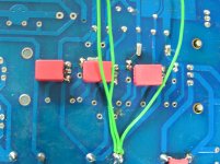
730user: the pictures I promised
phase:
I agree with you, it's a good regulator, but the the datasheet states 10uV/Vo, which means for every 1 Volt output, 10uV noise. So total noise is 10*5= 50uV
One advantage of this ON-semi reg is the ripple rejection, typically 83 dB at 120Hz, around 70dB until 10kHz. There's probably far more noise coming from the power supply than from the regulator's voltage reference after all.
730user: the pictures I promised
phase:
What jumper do you mean?The jumper really made a difference though, applied from the 47uf to the power pin, lowering the impedance to .1 ohm.
Attachments
Last edited:
Unfortunately the ripple rejection at higher frequencies of regulators in general is not too good.. Especially the digital supply is plagued by HF noise that is inadequately suppressed by regulators. You need extra measures...Hi Nosian,
I agree with you, it's a good regulator, but the the datasheet states 10uV/Vo, which means for every 1 Volt output, 10uV noise. So total noise is 10*5= 50uV
One advantage of this ON-semi reg is the ripple rejection, typically 83 dB at 120Hz, around 70dB until 10kHz. There's probably far more noise coming from the power supply than from the regulator's voltage reference after all.
730user: the pictures I promised
phase:
What jumper do you mean?
47ohm resistors, serie in output way!
thanx boys, more to learn.
btw in my board there 47ohm resistor just before then rca! I am taking them off! any comments?
thanx boys, more to learn.
btw in my board there 47ohm resistor just before then rca! I am taking them off! any comments?
The traces that connect the power pins on the op amps to the capacitor that is up stream, make sure that these are .1 ohm, if not, a tiny piece of wire will help.
The resistors that are in the output I have replaced with some caddock 12 ohm, helped things definitely.
The resistors that are in the output I have replaced with some caddock 12 ohm, helped things definitely.
I/U conversion? I'm allergic to resistors in audio path elsewhere.
why are they sitting there? is there any logic, or just old school books?
Orpheus bless us
why are they sitting there? is there any logic, or just old school books?
Orpheus bless us
This has been discussed some posts back. Two answers I can think of:I/U conversion? I'm allergic to resistors in audio path elsewhere.
why are they sitting there? is there any logic, or just old school books?
Orpheus bless us
- resistors are for short circuit protection of the op-amps in case op-amps are used with no internal protection
- resistors prevent op-amp output from accidental oscillating. This depends on how it is loaded, just a safety measure.
Last edited:
Just "recovered" from moving home but I think I need another two weeks to set up my gears because everything is still in a mess.
This dual AK4399 is making much attention in this forum because so far, this is the best DIY type DAC I ever heard. I have a twistedpearaudio ES9018 (2nd version) which is very dynamic and clean but lack of musicality in my system.
I just saw Aune (a product division of the largest DIY website www.hifidiy.net in China) is debutting a new DAC using AK4495S in end-October that I wonder if this could be a starting point for friends in diyaudio to build a "public pcb" for this DAC. Of course, first thing is to find out if AK4495S is a better alternative.
Any comment? Or should I start a new thread?
Hi Sunsun,
I've seen it and posted some info here, for sure it could be good to have another thread about it, that DAC looks promising...
Hi Nino,
if it's protection matter what should be the minimum value of the resistor? or just follow the pcb diagram? I think new version using 100ohm resistor...
I've seen it and posted some info here, for sure it could be good to have another thread about it, that DAC looks promising...
Hi Nino,
if it's protection matter what should be the minimum value of the resistor? or just follow the pcb diagram? I think new version using 100ohm resistor...
I'm not sure what article, but I read somewhere minimum value should be 100R to provide enough damping against oscillation. As far as I know, version 1 is also using 100R, at least in the schematic.if it's protection matter what should be the minimum value of the resistor? or just follow the pcb diagram? I think new version using 100ohm resistor...
- Status
- Not open for further replies.
- Home
- Source & Line
- Digital Line Level
- ebay:Weiliang Dual X2 AK4399 DAC with LCD