Cheaper, but very good..A reliable should more look like this one : AK4495 - I2S over USB Audio.... as you see it's not 30 bucks...
Products - I2S over USB Audio
http://www.diyaudio.com/forums/digi...mos-dsd-384-khz-32bit-usb-74.html#post4968597
I must agree, I put together one of these a D am very pleased with it. Sounds great.
PJN
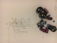
Here are pictures of the project thus far, as well as the offending capacitors...
I agree that as delivered, this really didn't sound all that great, still plenty of detail, but the iPad sounded better overall. This has been my experience with past boards from China.
No complaints now however, and I still really don't care about the other boards, am too busy to invest that much time honestly for diminishing returns. I make prototypes for a living and am well aware of the time that can be consumed with integration, that thread is telling. Looks fun I suppose, and much closer to diy than di buy.
These boards, warts and all, will go from mail box to music in minutes with a transformer and some juice...
Attachments

Looks good Phase!
Did you figure out: (1) the use of the double dipswitch next to the led and (2) how the reduce heat from the regulator next to the white 'AK4495+XMOS U8' marking on the board ?
Did you figure out: (1) the use of the double dipswitch next to the led and (2) how the reduce heat from the regulator next to the white 'AK4495+XMOS U8' marking on the board ?
I agree that as delivered, this really didn't sound all that great, still plenty of detail, but the iPad sounded better overall. This has been my experience with past boards from China...
So we must agree that boards from China are waist of time and money..
XMOS_AK4490 combo from my link sounds better than most commercial products..
So we must agree that boards from China are waist of time and money..
After 20 or so similar posts it seems more and more likely that you might have a problem with China
 😀
😀After 20 or so similar posts it seems more and more likely that you might have a problem with China
I don't have any more.. I had one, and learn my lesson..
After reading this part of forum seems that everyone who buy some of Chines products had few..
That regulator settled down after a day or so, still need to try and put some thermal grease behind it here one of these times, but it's much better now. I would be interested in getting out the scope to see if it is misbehaving.
I really should look into another source, for now it's a laptop. There's another thread that's based on a similar board that uses a 12s and there might be more there as far as finding a better source.
I suspect that the switches are in the same arrangement as on those boards as well, haven't checked that however. The current setting now works well with my magneplanar speakers. I do have some jumpers and pins here if I want to expiriment with that later.
At what point are your posts just slandering and trolling?
After looking at the last dac I made, where the capacitors for the snubbers on the rectifier diodes were attached to the case, am thinking that this time that the snubber circuits can be directly attached to the underside of the board.
At what point are your posts just slandering and trolling?
A bit heavy, don't you think? Some might get offended.
I managed to get the snubber circuits on under the board, used some Russian polystyrenes that I had. While these are great parts at bargain prices, they tend to take an extra long time to be at their best.
The values of .1uf in series with an 18ohm resistor, that combo in parallel with a.01uf on each transformer winding just fit, with the larger caps peeking out from under a bit. These values have worked very well on another dac with the same transformer.
Now to let it run for a good while...
The values of .1uf in series with an 18ohm resistor, that combo in parallel with a.01uf on each transformer winding just fit, with the larger caps peeking out from under a bit. These values have worked very well on another dac with the same transformer.
Now to let it run for a good while...
I'm wondering which characteristics are of higher priority in the selection of capacitors on the vref pins?
I have seen the suggested value of 2200uf shown in data sheets, however there was no mention of a voltage rating. I can assume that a standard type, of 10v, or 16v would be what was being referred to. I am wondering if a lower esr part in a higher voltage rating would net similar results here.
I have some 2200uf 35v parts I could just try, are a bit on the large(16mm dia) size...
AK4495 boards
Phase,
I’m back from vacation and find some time to answer your posts
About your post#38, what’s the issue with neg Vref ?. VREFLL (pin 37 & 36) & VREFLR (pin 19 & 20) have to be grounded, there’s nothing to bypass. VREFHL & VREFHR have to be bypassed by 100n MLCC and a large ecap (220u on appnote). AK4490 appnote described a relationship between this cap and low frequency THD, but I don’t know if 4490 and 4495 have the same out stage; it’s possible, they both support the trick to operate VDDLR and VREF at 7V with AVDD at 5V.
About your post#40, yes, I enjoy listening the dac. As described in ‘the Finally Weiliang released ak4495+ak4118 dac today’ thread, I mainly encountered 2 issues: sound was harsh in the mid and volume was too loud. I’ve done very few on the analog side, only fixed what, I believe, was part of harsh sound issue: power supply decoupling of the opa. I kept the two ecap but removed the 100n and replaced them by MLCC soldered on the pin of the socket, under the board. About the volume, I’ve deeply moded the board by replacing the 8051 MCU by an Arduino and took control of the AK4118 and AK4495 through software in order to get all of the chips features + remote control, additional input selector, memory, etc.…all except DSD.
About your post#41, it’s true but (IMHO) it doesn’t matter because we should consider that the RC network made of R9, R10, R11 and C8 is not part of the low pass filter build around the opa. R10 is negligible compared to R8 as R9 is compared to R7, so R10 and R9 have no impact on filter characteristics (fc, Q, G). I don’t know what AKM wants to achieve with this RC network, its fc is 30 MHz, same order of magnitude of AK4495 internal filter and converter clock frequency (close to 22 MHz) and far from opa filter fc (near 100 KHz). It may be a trick designed to get good performance figures on the datasheet. Answer or idea welcomed….!
About the two dip switches, you may have a look to post#54
http://www.diyaudio.com/forums/digi...liang-released-ak4495-ak4118-dac-today-6.html
And to post#109
http://www.diyaudio.com/forums/digi...iang-released-ak4495-ak4118-dac-today-11.html
Hope it was a nice vacation and all, thanks for reading that.
The difference in the resistors value will affect the offset from the filter circuit, as the pos/neg inputs will be altered. I did listen to the board with no op amp installed, wasn't half bad.
I plan on replacing the odd value that's on mine when I can get to the parts store.
The vref callout I had made regarding decoupling was off, the pin I was noticing had a lack of small ceramic cap was in fact the vcom or pin 35. So my bad there, is apparently no need for that there.
I like the arduino for control, good way to tap in to things that aren't available on this board otherwise. Maybe someday I will take the time to dig into that, when I have more time to spend on hobbies, sounds interesting.
My board came with some purple elnas, just after the regs, and samwha wf for decoupling, the more I replaced, the better it sounded, until they had all been replaced.
The 3.3k resistors have been replaced with the correct 3.6k, and the dc offset is down now to 15mv from 120mv.
It would be great to hear from others who have this board and their experiences.
It would be great to hear from others who have this board and their experiences.
The 3.3k resistors have been replaced with the correct 3.6k, and the dc offset is down now to 15mv from 120mv.
It would be great to hear from others who have this board and their experiences.
I get <2mV on both channels. USB plugged in, no signal, unmodified board.
Still waiting for my board from China... similar on DAC and filter stage, but with I2S input.
How to measure the DC offset? Just a DC voltmeter to the output with no signal?
How to measure the DC offset? Just a DC voltmeter to the output with no signal?
Still waiting for my board from China... similar on DAC and filter stage, but with I2S input.
How to measure the DC offset? Just a DC voltmeter to the output with no signal?
Usually for a power amp you should short the input to measure DC offset with a DMM.
Since I don't have a good schematics of this board I did not want to short (and maybe blow) anything.
Wow, those are great offset numbers!
What I thought was funny is that the correct values are listed underneath the components.
I also measured while powered on, but without music.
I may experiment with vref capacitors here and try to tighten up the bass a bit, not that it's bad, but I'm spoiled by my headphone setup. With that dac/headphone amp, the tight, pinpoint low bass notes came after using some mundorf ag main filtering capacitors. I would like to avoid that this time around if possible.
Yes, please post what you have done. I have ordered a similar DAC but with I2S entry. The layout of DAC and Output filter looks similar. It would be interesting what exactly you did, which parts were removed and which values you put as resistors and capacitors - maybe you could Show this on a photo of your board?
Thanks a lot!
I am interested in an I2S solution too. What and where did you get it? Can it work with a RPi 2? How about clocking it? Does it need a Masterclock. The DAC runs in slave mode, correct?
- Status
- Not open for further replies.
- Home
- Source & Line
- Digital Line Level
- Ebay USB DAC board