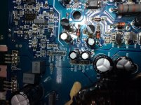
It’s IC5, I’ve attach picture of the location and screenshot from the diagram..
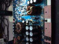
Also the amp has the same design to a large extent and similarities but the input board is design with slight differences using the same part numbers, the DUT (device under test) is a subwoofer bandpass 12v Earthquake branded unit.
Also the amp has the same design to a large extent and similarities but the input board is design with slight differences using the same part numbers, the DUT (device under test) is a subwoofer bandpass 12v Earthquake branded unit.
Attachments

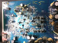
IC5 is in the feedback loop so the amp can be sensitive to changes. That said, most of the amps that I've repaired of this type use the 4560 or 4580.
Do I have this right. The 5532, no drive signals at the outputs FETs but you have them with the 4580?
Do I have this right. The 5532, no drive signals at the outputs FETs but you have them with the 4580?
Yes drive signal with 4560, but I thought my change was just replacing a bad chip as I said resistor R56 (68ohms) was burnt, I’m not sure, was thinking of getting a new chip.
Are you saying that the original wasn’t have to be bad?, is there another explanation?
Are you saying that the original wasn’t have to be bad?, is there another explanation?
I have never worked on this specific model so I don't have a definitive answer.
Does using the 4560 solve all of the problems?
Does using the 4560 solve all of the problems?
The 5532 is indeed bad, I’ve changed it and the drive wave is there when the fets are inserted.
Problem now is I’m not getting any audio and when the level is adjusted to about 12oclock the dc protect comes on, with or without fets, I’ve tried speaker on it and it blew the two test fets. Nothing is overheating at this point.
Problem now is I’m not getting any audio and when the level is adjusted to about 12oclock the dc protect comes on, with or without fets, I’ve tried speaker on it and it blew the two test fets. Nothing is overheating at this point.
Don't adjust anything on the amp. If you simply increase the level from the signal source, does the amp do the same thing?
What drive are you referring to? The input frequency or at about 80kHz?
Do you have rail-rail oscillation?
What drive are you referring to? The input frequency or at about 80kHz?
Do you have rail-rail oscillation?
The amp doesn’t protect when I increase the source (even max) also when I max the level control on the amp before powering it on, but if on while rotating the knob then it protects.
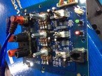
** where on these pads do I check for rail to rail oscillation? And is it with or without output fets?
** where on these pads do I check for rail to rail oscillation? And is it with or without output fets?
Attachments
You check for r-r oscillation on the terminals of the outputs that connect to the output filter inductor.
Probe ground on speaker ground reference and Im not getting a r-r oscillation, should I check with the fets in? That’s the only times I would see some sort of waveform; all I’m getting is just dc volts 50+.
You stated that you were getting drive signals. Where did you see them?
You only get r-r when the output stage is operating.
You only get r-r when the output stage is operating.
I’ve just found a bad transitor in the drive circuit, MPSA56 must have been blown when the fets failed. Can a mpsa92 or 42 be used for the moment?
The only time I see any oscillation is when the fets are installed (2pcs one per bank) 4pcs the amp uses. I’m not seeing anything on the scope but a dc line 50+ volts. Should I insert the fets and send you picture?
Don't install the outputs.
For other amps of this type, you can check the drive at the outputs without them being installed. I don't see anything that would prevent that here.
Is the jumper off of PTC2?
Are you seeing the drive signal swinging ±15v on the output of the 4560 (pin 1 of IC5)?
For other amps of this type, you can check the drive at the outputs without them being installed. I don't see anything that would prevent that here.
Is the jumper off of PTC2?
Are you seeing the drive signal swinging ±15v on the output of the 4560 (pin 1 of IC5)?
If that's swinging rail-rail, you can ignore post 37.
If you install the outputs and clamp them and just adjust the level with the signal source, do the outputs fail?
If you install the outputs and clamp them and just adjust the level with the signal source, do the outputs fail?
Yes jumper is off, but no audio (I have my multimeter on millivolts ac at speaker terminal) not seeing increase in value when I attenuate the source and just some spikes/bumps when notched the amp level gain.
Not seeing any playing rise in the waveform either. Where on the board could I test for audio is S-IN probe-able?
The mosfets both power and output has no heat currently.
Not seeing any playing rise in the waveform either. Where on the board could I test for audio is S-IN probe-able?
The mosfets both power and output has no heat currently.
Attachments
We're not being clear on the details which is making this difficult.
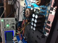
On your scope, precisely what point was the scope connected to?
On your scope, precisely what point was the scope connected to?
- Status
- Not open for further replies.
- Home
- General Interest
- Car Audio
- Earthquake Sub Box Amp Module D200W-M