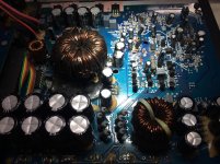
Hey guys im having problems with this amp module actually its a powered subwoofer but built as a standard class d car amp (12v).
Im getting a burst of dc on the output then the amp goes into protect (dc protect) (it has thermal, over-current and dc protect led) I've check all the transistors in the audio drive circuit for the Hi and Lo drives,it uses a LM311 also. Ive changed the LM339 twice before i actually test the speaker ouput with my probes, would there be DC on the output without no out put FETS (45N20B) installed?
Im getting a burst of dc on the output then the amp goes into protect (dc protect) (it has thermal, over-current and dc protect led) I've check all the transistors in the audio drive circuit for the Hi and Lo drives,it uses a LM311 also. Ive changed the LM339 twice before i actually test the speaker ouput with my probes, would there be DC on the output without no out put FETS (45N20B) installed?
Attachments

Did you pull the drivers to check for leakage and open junctions?
If you solder a bridge between terminals 1 and 2 of PTC2, does it go into protect or produce DC at the output?
If you solder a bridge between terminals 1 and 2 of PTC2, does it go into protect or produce DC at the output?
The bridge on PTC2 doesn’t come on with any error signal nor with dc on the output, I didn’t get a drive wave HI side or LO side either on the outputs.
Are you saying the amp powers up (produces rail and regulated voltages) without going into protect?
Absolutely Mr. Babin.
All the necessary voltages are present from the PS section 103.7vp-p.
No drive wave.
All the necessary voltages are present from the PS section 103.7vp-p.
No drive wave.
Did you pull the drivers to check for leakage and open junctions? The drivers in this type of amp (all early versions like this) tend to run hot and fail without always shorting.
Do you have good signal coming into the amplifier stage from the preamp stage? Without the feedback from the output, it may just be a square wave but shouldn't be straight DC.
Do you have good signal coming into the amplifier stage from the preamp stage? Without the feedback from the output, it may just be a square wave but shouldn't be straight DC.
I’ve checked but not changed all transistors in the drive circuit I didn’t find any one faulty, but in the past I’ve come across transistors that can read good and not performed as expected.
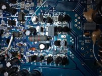
Q19 and Q33 is the two transistors with exceptionally heat, I didn’t put any signal to it as the potentiometers are not conducting (the rivets are bad) but I fixed another of this amp and drive signal was present even without input.
The input board just needs the pots.
Q19 and Q33 is the two transistors with exceptionally heat, I didn’t put any signal to it as the potentiometers are not conducting (the rivets are bad) but I fixed another of this amp and drive signal was present even without input.
The input board just needs the pots.
Attachments
You could jump the pots out to get signal through for testing.
If you remove the outputs, does the amp come on without going into protect (solder/jumper not on opto)?
If you remove the outputs, does the amp come on without going into protect (solder/jumper not on opto)?
With or without the outputs (I’m using 2pcs, the other 2pcs was blown, that’s how I receive the amp 45N20B) once the jumper/solder is not in place it goes to protect.
Remove the outputs and clean the solder pads and confirm that there is no bridge between the pads.
Did you do what's needed to get signal into the amp?
Did you do what's needed to get signal into the amp?
If you remove the short on the opto and remove PTC1 (I'm not sure that bridging the input is safe), does the amp go into protect?
No I haven’t a diagram for this amp, the best was I’ve done repair on another same module but I’ve handed over to the customer already.
Could the drive stage needs new parts most my changes are pulls from other amp.
Is there any other test that can be done, is the LM311M ok?
Could the drive stage needs new parts most my changes are pulls from other amp.
Is there any other test that can be done, is the LM311M ok?
If you removed the second opto, that should have taken the LM311 out of the equation.
Does the amp draw excessive current if you connect a load across the speaker terminals without the output transistors in place?
This is the diagram I'm using. Is it close?
http://www.bcae1.com/temp/sony - XM-D400P5_Car Power Amplifier SM.pdf
Does the amp draw excessive current if you connect a load across the speaker terminals without the output transistors in place?
This is the diagram I'm using. Is it close?
http://www.bcae1.com/temp/sony - XM-D400P5_Car Power Amplifier SM.pdf
No, no current draw, not even heating of the outputs when installed just not getting any drive wave. Do you think I should rebuild the drive circuit?
Can the NJM5532 op amp ic cause such problem?, as I’ve changed which I should have done because I’ve found a defective 68ohms smd resistor looking burn in the final preamp stage with a value of 200+ ohms. I did change the resistor before all the test but it’s when I changed the ic to a 4580 then the drive signals appear, doubtful I restore the original part and drive waves disappear, what could be a replacement if I’m having an had time to get that part in my locale for that chip?
Is that op amp a part of the drive circuit?
Is that op amp a part of the drive circuit?
Which op-amp are you referring to? Find the corresponding part on the diagram for the sony I posted.
- Status
- Not open for further replies.
- Home
- General Interest
- Car Audio
- Earthquake Sub Box Amp Module D200W-M