I'm in the process of going through an H.H. Scott 348 (not the "B" version"). One amp board is ok, but the other has two bad drivers: Q5 and Q6. Based on the fact that the outputs are both non-original 2N3055s (tested ok), my guess is that one or both of the original Bendix outputs on this side shorted and the person doing the repair never checked the drivers. Or not. . . . Regardless, I'm going to pull the board and check everything.
The failed Q5 and Q6 are what H.H. Scott called "QA-10" transistors. According to a circa 1980 SK catalog I have, this crosses to SK3024/ECG128. If I have to go with NTE128s, I will, but I could use input on a) whether there are any better options, such as the 2N3019, and b) how to address the color-coded grading that Scott used for these, which I assume correlated to hFE and possibly other parameters.
The failed Q5 and Q6 are what H.H. Scott called "QA-10" transistors. According to a circa 1980 SK catalog I have, this crosses to SK3024/ECG128. If I have to go with NTE128s, I will, but I could use input on a) whether there are any better options, such as the 2N3019, and b) how to address the color-coded grading that Scott used for these, which I assume correlated to hFE and possibly other parameters.
Attachments


Q6, it is desirable to use with the maximum available Hfe. Q7 can be less than or equal to Hfe.
Last edited:
Thanks. After some further digging, it appears that QA-10 was a 2N3053 (hand-selected, per the colors). The Vceo for the 2N3053 seems borderline for Q5. Thoughts on going with the 2N3053A or 2N3019 instead?
The 2N3053 Multicomp 50hFE is commercially available for $ 6. If you do not pursue the goal of achieving complete authenticity, many general-purpose transistors TO-92 or TO-126 will do. The 2N3053а and 2N3019 looks good.
Last edited:
TO92’s won’t do, unless you happen to have some of the old tall cased ones which are good for a watt and one amp of current. Modern TO-126 cased “driver” transistors work well (like C2960/A1220) - better than the vintage TO-39’s with limited hFE - but are rapidly disappearing from the market. Many of the older MJE TO-126 types will work, but are NOT an upgrade from the TO-39’s (some are much slower). Any of the 80 volt 1 amp TO-39’s will do. If they come from the likes of Central, Multicomp, or NTE you are likely getting the exact same part regardless of the type number on the case. The NTE 128/129 equivalents. And paying $6 apiece for them. If you want it to look and feel original, by all means. But I’d stick in the modern Fairchild drivers myself.
TO92’s won’t do, unless you happen to have some of the old tall cased ones which are good for a watt and one amp of current. Modern TO-126 cased “driver” transistors work well (like C2960/A1220) - better than the vintage TO-39’s with limited hFE - but are rapidly disappearing from the market. Many of the older MJE TO-126 types will work, but are NOT an upgrade from the TO-39’s (some are much slower). Any of the 80 volt 1 amp TO-39’s will do. If they come from the likes of Central, Multicomp, or NTE you are likely getting the exact same part regardless of the type number on the case. The NTE 128/129 equivalents. And paying $6 apiece for them. If you want it to look and feel original, by all means. But I’d stick in the modern Fairchild drivers myself.
Appreciate the perspective. (I assume you meant KSC2690.)
I could also use suggestions for what to sub in for the SRI-5 diodes at D1, D101, and D102. The latter two form what Scott called the stabistor diodes.
Drivers replaced, along with one bad emitter resistor. Now I need to set the bias, however, the Scott service manual doesn't give a figure to shoot for--just an indication of the test points on the schematic (and handy dandy access on the back). Any suggestions?
Attachments
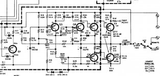
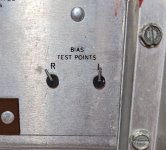
R31 - setting half of the DC voltage at the output (35V). R32 - bias, test point R114 6-10 mV (relative to ground).
Thanks. I went to set the bias, and it's fluctuating wildly in the repaired right channel--anywhere from 0mV to 70mV. The bias trimmers are turned CCW in both channels, which gives me an approximate bias of zero in the "good" left channel. The resistance between legs and from the wiper to each leg in the right side bias trimmer checks out ok--roughly the same as the left.
What's been done:
What's been done:
- Q5 and Q6 have been replaced with 2N3019s.
- R113 replaced with .82 ohm 5W wirewound.
- Q1 replaced with a 2N3711
- Q2 replaced with a 2N3710
- Q3 and Q4 pulled and tested ok.
- Q110 and Q111 pulled and tested ok.
- D101 and D102 tested in circuit and compared to good left channel. Ok.
- Set DC Balance for both channels to 37V, half of measured 75V rail voltage.
Checked the following since my previous post:
- R19 and R22
- The output caps for both channels.
Those old Scott receivers were built nice!
I've got a 382 Stereomaster in beautiful condition posted for sale on C-list.
Very sensitive tuner section!
Of course, I've gone over the whole chassis to perform like new.
Plus the walnut cabinet is a particularly odd version with a neat lattice-cut ventilation panel on top.
Others I've seen used a plain metal grille.
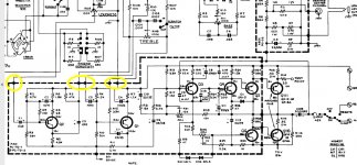
The way the amp boards are situated fairly close to each other, taking voltage measurements from certain spots is going to be a little dicey with respect to avoiding a probe slip/inadvertent contact. This, plus the fact that I haven't found a bad cap, resistor, diode, or transistor on the problem board has me wanting to explore another possibility first, namely that something from prior to the inputs is upsetting the board. Rather than desolder each wire from its terminal on the amp board, I'm thinking I'll jumper them to ground one by one (provided the DC is negligible), while monitoring the bias to see if it stabilizes at any point. Thoughts?
Attachments
No scope? You could have subsonic oscillations or a noisy transistor in that channel in the gain stage ahead of the tone control or a variety of other issues I can't even guess at.
I had a 348B two decades ago, the ex got that. Did a lot of work on that unit, sounded pretty good for the time I thought.
I had a 348B two decades ago, the ex got that. Did a lot of work on that unit, sounded pretty good for the time I thought.
- Home
- Amplifiers
- Solid State
- Early Solid State: H.H. Scott 348 Receiver