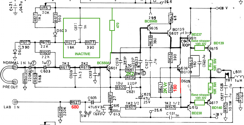
C615 and C625 are crucial so should have excellent specs. C603 and C605 are important too. In softclip mode, C605 can ruin the amp easely. Avoid this SC thing better. In the drawings, it appears that C603 is wrongly polarised, it should be as C604; positive pole on R605, neg on R603. Check dc value at nodes between C601-C603 / C602-C604 anyway and check position of caps is right.
Q's 609/610 must be mounted on the heatsink. If the omitted diode was put there, the bjt's have to take over.
C615/6225 ar Nichicon UVY and UPW respectivly so not bad caps I guess. C603/605 where tantalum, I replaced them With Polyester film caps (non polar)
Thanks a lot,
So If I understood everything well, here is the schematic with the test rig:
I'm not good enough to find the component values for the current source topology you posted, I 'll need help on this subjet if it happens to be necessary.
Q205 is a N-channel Fet right? and Q206 is supposed to be Q601 in the NAD schematic? So the whole topology replaces C611/Rr621/R623/R629/Q603 and C617, right?
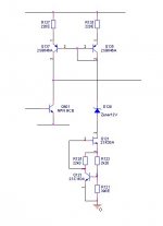
The compound current source is stand alone, topped with a pnp-pnp current mirror, as combination replacing the nad current source around Q603. So Q601 stays in position.
Start with the 470E resistor and if that's working ok, we can replace it with this better current source.
I make you a drawing of the intended circuit (after dinner).
Part of a circuit I'm working on, a bit tweaked for this purpose.
R121 sets the current, here approx 0.6 / 390E = 1.5 mA.
You can use a wide variaty of N-channel J-fets and bjt's, just take what is available. Also the pnp-pnp mirror is not critical. Any make will do.
R121 sets the current, here approx 0.6 / 390E = 1.5 mA.
You can use a wide variaty of N-channel J-fets and bjt's, just take what is available. Also the pnp-pnp mirror is not critical. Any make will do.
Attachments
hello everyone .. first of all I apologize for my translation (I don't speak english)
i had the same problem nad 3020 first model
R652 as burnt, destroying Q610 / 612/614 and both power trans Q616 / 618 where they were fried.
The left channel is intact.
I will also change Q612 / 614 to BD139 / 140 as the original is not easily obtainable. (Changing the pinout)
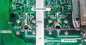
I have read from several parts and here too the advice / need to isolate the emitters and insert a 0.33 ohm 3w resistor between the emitters and the common connection point.
and also insert a 4.7 ohm 3w resistor between the drivers and the bases
Without this mod there is a risk of thermal runaway due to the newer transistors which are of epitaxial construction. The original 2955/3055 pair was hometaxial.
x to put it into practice, for me it is difficult because I am not very practical, but a great desire to learn
I ask you if this screen of mine is correct to run the mod
i had the same problem nad 3020 first model
R652 as burnt, destroying Q610 / 612/614 and both power trans Q616 / 618 where they were fried.
The left channel is intact.
I will also change Q612 / 614 to BD139 / 140 as the original is not easily obtainable. (Changing the pinout)
I have read from several parts and here too the advice / need to isolate the emitters and insert a 0.33 ohm 3w resistor between the emitters and the common connection point.
and also insert a 4.7 ohm 3w resistor between the drivers and the bases
Without this mod there is a risk of thermal runaway due to the newer transistors which are of epitaxial construction. The original 2955/3055 pair was hometaxial.
x to put it into practice, for me it is difficult because I am not very practical, but a great desire to learn
I ask you if this screen of mine is correct to run the mod
Attachments
NAD 3020 SERIES 20 REPAIR
Hi,i have repair this with bd 139/140 driver ,change pin ,power transistors series ST and emitter resistence with trimmer 1k for idle current and recap i live in Italy if you have any problem osvaldo.figini@alice.it
Hi,i have repair this with bd 139/140 driver ,change pin ,power transistors series ST and emitter resistence with trimmer 1k for idle current and recap i live in Italy if you have any problem osvaldo.figini@alice.it