My EAR 834 clone when switched on for testing, after measuring the AC something seemed up as I got 26.83 volts then I noticed a whisp of smoke. So turned it off straight away and unplugged it. However cant seen to locate the issue anyone have any Ideas?
Well, if there is not a factor 10 in reading of the scale, it's a no-brainer.
Just follow each wire back to the mains socket, measuring as you go.
Eventually you'll find the problem.
Assuming as noted in the first sentence.
Jan
Just follow each wire back to the mains socket, measuring as you go.
Eventually you'll find the problem.
Assuming as noted in the first sentence.
Jan
I would first measure resistances with power off and disconnected from the mains to make sure that all wires are as they should be and no shorts.
If that works out, scrutinize the connections to the power transformer. A short there or wrong connections may cause a short to the mains and smoke.
Logical, step by step. Be mindful that if you build the amp, it is very much likely that you made a mistake.
Silence your ego! 😎
Jan
If that works out, scrutinize the connections to the power transformer. A short there or wrong connections may cause a short to the mains and smoke.
Logical, step by step. Be mindful that if you build the amp, it is very much likely that you made a mistake.
Silence your ego! 😎
Jan
Ok i will take a look today… i was also thinking in the boltage regulatory as i used the flip side of the board…. Thinking i might of got that the wrong way round.
Maybe first step is to verfy you have mains voltage at the point where it enters the board, but without the board connected. That makes sure that all wiring between mains socket and board entry point is correct.
Jan
Jan
Ideally you'd put a light bulb in series with one mains lead to limit current in case of trouble, hang your DC voltmeter on the first elcap after the bridge rectifier and switch on. See what that gets you.
Jan
Jan
So that seems a clear pointer. Assuming there is 230V between the two wires at the plug, why not at the other end of the wires?
Follow that. Check continuity of each wire with the ohm meter (without power of course!)
Edit: remove the mains wires from the board. Then check continuity of each wire from the mains cord plug to the wire ends at the board.
If that checks out, carefully plug in the mains cord and check with the ac voltmeter if you have 230VAC between the two phase wires at the board side.
As I'm sure you know, there's not 230VAC 'at a wire'. There's 230VAC between two wires.
Jan
Last edited:
Hi Jan appreciate the help, this is only the second amp ive built ans im still learning alot. My fault findind skills are not great. Sorry to ask this i know how the continuity works on the meter, what im not certain about is from which point to which point i need to place the probes. As this is the first time i had an issue with a power supply
Forget about amps and power supplies. This is basic electricity.
You really should read up on this. You want to build/modify/repair amps, at the very least you should learn how to measure the resistance of a wire to check if it is broken.
I suggest to consult the net, search with Google, there's a ton of material out there.
Jan
You really should read up on this. You want to build/modify/repair amps, at the very least you should learn how to measure the resistance of a wire to check if it is broken.
I suggest to consult the net, search with Google, there's a ton of material out there.
Jan
Ok i removed the 230 wires from the board and do not appear to be getting any continuity from the mains plug input to either wires

But you did measure 53Vac so where did that come from then?
How did you measure the continuity? What exactly did you do?
Edit: you may have been measuring stray voltage between one of the phases and the mains safety ground wire.
For now, forget that safety wire.
What you are after is the line and neutral wires.
Jan
How did you measure the continuity? What exactly did you do?
Edit: you may have been measuring stray voltage between one of the phases and the mains safety ground wire.
For now, forget that safety wire.
What you are after is the line and neutral wires.
Jan
Last edited:
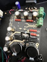
1. The 50 volts vac came from the 1st green socket on the board in the pic it came from measuring across that.
2. The continuity came from attaching the probe at one end of the red wires taken out of the socket in the board, the other end to the wire from the transformer to the input power socket. Also same wire at the on off switch.
2. The continuity came from attaching the probe at one end of the red wires taken out of the socket in the board, the other end to the wire from the transformer to the input power socket. Also same wire at the on off switch.
Ok ive checked again
1. Between line and seperately each red wire
2. Between neutral and seperately each red wire
Using continuity and im getting infinitive, which leads me to believe the transformers faulty right?
1. Between line and seperately each red wire
2. Between neutral and seperately each red wire
Using continuity and im getting infinitive, which leads me to believe the transformers faulty right?
- Home
- Amplifiers
- Tubes / Valves
- Ear834 clone power supply issue