Hi,
Can anyone help me identify the input blocking capcitor on the attached photo? I've tried tracing the pcb but jsut getting a headache!
Thanks in advance!

Can anyone help me identify the input blocking capcitor on the attached photo? I've tried tracing the pcb but jsut getting a headache!
Thanks in advance!
You could try with a multimeter in resistance mode, following the continuity from input connector into the unit.
Tracing on sight is hard and error prone.
Jan
Tracing on sight is hard and error prone.
Jan
Thanks. I've tried that and come to a cap which appears to connect to the input grid but shorting that gives silence!
The multimeter gets me to the two inner rear brown film caps nearest the input sockets but shorting these is what leads to silence. That correlates to the same input caps on the 859.
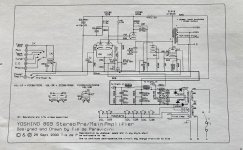
I've just stumbled across a circuit diagram and now I can see that the circuit won't work without an input blocker: it just needs a better one!
That's possible, depending on the circuit, it can upset the grid bias.
Is the far side of the cap connected to the grid, probably through a low value grid stopper?
Jan
Is the far side of the cap connected to the grid, probably through a low value grid stopper?
Jan
Yes, but it also connects to a feedback loop from the output valve so shorting that stops the circuit functioning. It's a little special the Tim De Pavaricini enhanced single ended circuit
I dont know the 869, just the 834. Layout looks a bit similar.
The C110 cap is likely the first cap on input. Thats the square looking ones.
Also, consider replacing that bipolar electrolytic that is adjacent to the tubes on each side. Thats the output cap.
The C110 cap is likely the first cap on input. Thats the square looking ones.
Also, consider replacing that bipolar electrolytic that is adjacent to the tubes on each side. Thats the output cap.
Of course that's right but I do understand the circuit and and have measured that there's only the usual tiny bias voltage on the input valve. The only part that was a mystery and caused the issue, is that EAR in their wisdom have installed a two resistor attenuator on the 'power amp in' switch, not shown on the circuit diagram, which gives an earth path if you remove the input blocking capacitor.Never "short a capacitor" unless you first understand the circuit completely.
EAR 869 input tube grid at about +20V, so shorting 1uF 63V input capacitor would possible damage the previous stage (if it's SS).

http://www.troelsgravesen.dk/EAR-869.htm

http://www.troelsgravesen.dk/EAR-869.htm
The previous stage is tube and has an output blocking capacitor, so the 869 is just doubling up. It would work perfectly apart from the voltage divider on the input sockets (not on circuit dia) which provides an earth path. I'll measure the resistance of the divider as it may not be necessary
Its part of the DC feedback loop setting the bias for the output tube. Would be cautious with changing the uF as it may have some effect on the DC stability.
The output tube bias current is controlled by a DC feedback loop from output cathode to the positive dif. input grid.Never "short a capacitor" unless you first understand the circuit completely.
Shorting the positive dif. input tube capacitor removes the bias servo feedback loop.
The output tube will then likely be drawing extra current while the input cap is shorted. Hopefully there is lots of margin in the output circuit!
I second the caution that any value changes in capacitor in this loop could well result is stability issues in the DC feedback loop.
- Home
- Amplifiers
- Tubes / Valves
- EAR 869 Input Blocking Caps