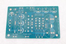
I've ordered these two boards to make an EAR 834 clone but I can't work out from the PSU board whether it's designed to produce 6.3 or 12.6v heater voltage. The seller isn't responding and I want to get a transformer ordered. Can anyone shed any light on this please?
1set Gold Stereo tube Pre-amp MM RIAA EAR834 phono 12AX7/ECC83 Assembled Board | eBay
1set Gold plated tube preamplifier HVDC285V Powr supply PCB assembled | eBay
1set Gold Stereo tube Pre-amp MM RIAA EAR834 phono 12AX7/ECC83 Assembled Board | eBay
1set Gold plated tube preamplifier HVDC285V Powr supply PCB assembled | eBay
Attachments
Last edited:
Actually you can do both 6.3V and 12.6V with this board - it's just a rectifier with a CRCRC filter.
However the design this was cloned from is intended to get 6.3VDC from the 6.3V/2A transformer winding. And given that 16V rating of the capacitors is a bit too low for 12.6V application, and that you'll have to play with R values in the filter to get to the desired voltage in this case, I'd go for 6.3V option.
However the design this was cloned from is intended to get 6.3VDC from the 6.3V/2A transformer winding. And given that 16V rating of the capacitors is a bit too low for 12.6V application, and that you'll have to play with R values in the filter to get to the desired voltage in this case, I'd go for 6.3V option.
Do yourself a favour and remove the red Wima caps and replace with something better. Even entry level Mundorfs, Cornell-Dublier 940C or 942C of Obligato Golds would be better. Humble Homemade Hifi - Cap Test
Steve
Steve
Do yourself a favour and remove the red Wima caps and replace with something better. Even entry level Mundorfs, Cornell-Dublier 940C or 942C of Obligato Golds would be better. Humble Homemade Hifi - Cap Test
Steve
Because they are Wima or because they are 99% certainly fake Wima?
Transformer
Transformer? This worked for me, not expensive for a C-Core.
115V/230V 30W R-Core Transformer for Tube Amplifier Preamps 9V+9V+9V 6.3V 240V | eBay
Transformer? This worked for me, not expensive for a C-Core.
115V/230V 30W R-Core Transformer for Tube Amplifier Preamps 9V+9V+9V 6.3V 240V | eBay
EAR834 with a source follower instead of third tube
Hello,
as we are talking about the EAR834 here - has anyone tried to swap the third tube (working as a cathode follower) to a MOSFET source follower? I'm wondering whether the feedback loop will operate properly. I already have a chassis with two noval sockets for stereo phono preamp, that's why I think about the modification of EAR. I thought about applying the STU9HN65M2 transistor (the same as EL34 drivers in Baby Huey amp). Please share your thoughts.
Rgds
MODS, MODS, MODS
My main dislike of the 834P is the 12AX7 cathode follower output. I can see changing it over to a MOSFET or if staying all tube change it to a 12AT7 with one resistor change.
(Why did EAR go with all 12AX7s? My suspicion: Using 3 tubes all the same gave them a 1 in 3 chance of finding a quiet one for the V1 position (the only spot that needs a quiet tube) from any 3 tubes grabbed from the parts bin.)
Thorsten Loesch's mods to the 834P are more extensive. See link below. One thing he does is eliminate the coupling cap between the second and third stages.
You might have to search the web for the 834P schematic but it's out there and easy to find.
There's also a thread about this preamp on the Lenco Heaven forum.
My choice for a decent phono is the Broskie Tetra on the Tubecad.com site. More expensive than the 834P clones but worth it for its higher performance.
Cheers, Steve
The very much non-definitive EAR 834P Modification Guide - Thorsten - Vinyl Asylum
Hello, Everyone.
I am quite new to this site and novice in building DIY Electronics. Got EAR 834P Clone and the PCB look very high quality and just completed putting together.
Good news is that Right Channel works without any hum and sounds nice. Bad News is that there is no sound at all on Left Channel. I guess that it is better than no sound on both channel but no idea what to check and make this work.
Here are things that I checked so far.
+ 3 x 12AX7 Tubes. Checked with 2 different sets (each set 3 tubes) and result is same so no tube issues.
+ Signal In and Out cables (RCA sockets to PCB Joints) are checked with Multimeter for conductivity and they are fine.
+ All solder joints were triple checked and made sure no cold solder
+ Original 2K 3W resistors were out of value so got replacement one from RS Online and replaced.
+ Measured DC voltage from Power Supply Board and Main Board. Power Supply Board DC Out is 6.49v and Main Board DC IN is 6.34v with tubes installed.
This is first attempt for DIY build and If anyone can recommend a thing or two, it would be hugely appreciated.
I attached photo of the current status for reference.

If anyone can enlighten me on this, would be super appreciated. Thank you...
I am quite new to this site and novice in building DIY Electronics. Got EAR 834P Clone and the PCB look very high quality and just completed putting together.
Good news is that Right Channel works without any hum and sounds nice. Bad News is that there is no sound at all on Left Channel. I guess that it is better than no sound on both channel but no idea what to check and make this work.
Here are things that I checked so far.
+ 3 x 12AX7 Tubes. Checked with 2 different sets (each set 3 tubes) and result is same so no tube issues.
+ Signal In and Out cables (RCA sockets to PCB Joints) are checked with Multimeter for conductivity and they are fine.
+ All solder joints were triple checked and made sure no cold solder
+ Original 2K 3W resistors were out of value so got replacement one from RS Online and replaced.
+ Measured DC voltage from Power Supply Board and Main Board. Power Supply Board DC Out is 6.49v and Main Board DC IN is 6.34v with tubes installed.
This is first attempt for DIY build and If anyone can recommend a thing or two, it would be hugely appreciated.
I attached photo of the current status for reference.
If anyone can enlighten me on this, would be super appreciated. Thank you...
Start by checking the cathode voltage of the first triode (2k2 resistor), cathode voltage of the second triode 2k2 resistor and cathode voltage at the output CF 120k resistor.
If those are ok and there are no cold joints on the board look at the coupling caps.
If those are ok and there are no cold joints on the board look at the coupling caps.
Last edited:

I found the cathode resistor R4 (2.2K) in Stage 1, cathode resistor R5 (2.2K) in Stage 2, cathode resistor R6 (68K) in Stage 6 as highlighted on attached photo.
I am not 100% sure where to put +/- throbe of Multimeter to measure and what value should I expect from the measurement.
Sorry for asking novice questions.

I am not 100% sure where to put +/- throbe of Multimeter to measure and what value should I expect from the measurement.
Sorry for asking novice questions.
- Status
- This old topic is closed. If you want to reopen this topic, contact a moderator using the "Report Post" button.
- Home
- Amplifiers
- Tubes / Valves
- EAR 834 clone