Hi,
I am having trouble finding (or designing) a Eagle3D/POV model for a Silver Mica cap. The problem is the shape of the Silver Mica cap is a complex surface and I am only capable of simple boxes or cylinders. 😀
I have looked numerous times on the web for a suitable model but can't find anything to I can use.
The POV's Complex Blob Construct is probably to way to go but I am having difficulty getting reasonable results.
Any POV experts out there that can help?
regards
What part number for the cap, and can Eagle import STEP, STL or similar?
Hi marce,
Thanks for responding. 🙂
Here is the datasheet for a typical Silver Mica cap.
http://www.cde.com/catalogs/STD-DIPPED.pdf
I'll have to do some research on STEP or STL.
It's really is a POV issue, rather than an Eagle issue.
Eagle3D (not part of Eagle) is just a ULP (user language program) that converts an Eagle PCB into a 3D POV model. The problem is I don't have the macro for a Silver Mica Cap. At the moment I just output the Silver Mica Cap as a ceramic cap. For example C4 in this picutre: http://www.diyaudio.com/forums/software-tools/183841-mjl21193-4-eagle-2.html#post2494692
regards
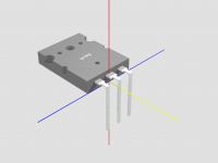
1st attempt, based on the CD15CD010DO3F part. It is a parametric model so I can scale it in SolidWorks. Dont know much (well anything!) about Eagle/POV, but most 3D software can import STEP format. Wouldn't mind more info on POV.
Had to try and guess overall shape from data sheet! and a bit rusty at modeling in 3D these days so it looks a bit lumpy, but can fine tune it.
Had to try and guess overall shape from data sheet! and a bit rusty at modeling in 3D these days so it looks a bit lumpy, but can fine tune it.
Attachments

hi marce,
Thanks, that looks more than satisfactory for my use.
Now to get it into a format I can use.
POV is more of a ray tracing program than a 3D modeller. Here's some info:
POV-Ray - The Persistence of Vision Raytracer
Looks like POV can accept STL but not STEP files.
POV-Ray: Newsgroups: povray.advanced-users: Conversion from STEP to Pov
After a bit of reading about blobs it seems they might be a bit buggy so I am a little concenrned that a conversion process might present more problems. Then again the conversion process may not use blobs.
Here's the limit of my 3D capabilities:
Which produces:
Thanks, that looks more than satisfactory for my use.
Now to get it into a format I can use.
POV is more of a ray tracing program than a 3D modeller. Here's some info:
POV-Ray - The Persistence of Vision Raytracer
Looks like POV can accept STL but not STEP files.
POV-Ray: Newsgroups: povray.advanced-users: Conversion from STEP to Pov
After a bit of reading about blobs it seems they might be a bit buggy so I am a little concenrned that a conversion process might present more problems. Then again the conversion process may not use blobs.
Here's the limit of my 3D capabilities:
Code:
/**********************************************************************
* TO3P package
* Written by: Greg Erskine
* Date: 1 May 2005
* Version 0.02
**********************************************************************/
#macro USER_TO3P(value,H_V)
    // Values taken from Motorola Semiconductor Technical Data sheet
    // for the MJL21193/MJL21194 in the form max - (max - min) / 2

    #local A = 29    - ((29.0  - 28.0)  / 2);
    #local B = 20.3  - ((20.3  - 19.3)  / 2);
    #local C =  5.3  - (( 5.3  -  4.7)  / 2);
    #local D =  1.48 - (( 1.48 -  0.93) / 2);
    #local E =  2.1  - (( 2.1  -  1.9)  / 2);
    #local F =  2.4  - (( 2.4  -  2.2)  / 2);
    #local G =  5.45;
    #local H =  3.0  - (( 3.0  -  2.6)  / 2);
    #local J =  0.78 - (( 0.78 -  0.43) / 2);
    #local K = 18.8  - ((18.8  - 17.6)  / 2);
    #local L = 11.4  - ((11.4  - 11.0)  / 2);
    #local Nmax = 4.75;
    #local Nmin = 3.95;
    #local P =  2.6  - (( 2.6  -  2.2)  / 2);
    #local Q =  3.5  - (( 3.5  -  3.1)  / 2);
    #local R =  2.35 - (( 2.35 -  2.15) / 2);
    #local U =  6.5  - (( 6.5  -  6.1)  / 2);
    #local W =  3.2  - (( 3.2  -  2.8)  / 2);
    #macro TextWidth( Text, Font, Size )
    #local T1 = text { ttf Font concat("|",Text,"|") 1 0 scale <Size, Size, 1> }
   #local T2 = text { ttf Font "||" 1 0 scale <Size, Size, 1> }

 ((max_extent(T1).x - min_extent(T1).x) - (max_extent(T2).x - min_extent(T2).x))
    #end

    // Plastic package with value engraved
    union {
      object {
        difference {
          box { <-B/2,0,0> <B/2,C,A-P> }
          // hole
          cylinder { <0,-1,A-P-U> <0,C+2,A-P-U> Q/2 }
          // half holes on sides
          cone { <-B/2,E,A-P-U> Nmax/2 <-B/2,E+C,A-P-U> Nmin/2 }
          cone { < B/2,E,A-P-U> Nmax/2 < B/2,E+C,A-P-U> Nmin/2 }
          cone { <-B/2,E,L>     R/2    <-B/2,E+C,L>     R/2-0.2 }
          cone { < B/2,E,L>     R/2    < B/2,E+C,L>     R/2-0.2 }
          // dimples
          cone { < B/4,C-1.2,A-P-U> Nmax/5 < B/4,C+1,A-P-U> Nmin/5 }
          cone { <-B/4,C-1.2,A-P-U> Nmax/5 <-B/4,C+1,A-P-U> Nmin/5 }
          cone { < 0,C-1.2,L/2> Nmax/5 < 0,C+1,L/2> Nmin/5 }

          #local Twidth = TextWidth( value, besch_font, 2 );
          text { ttf besch_font value 1, 0 pigment { White } scale <2,2,1> rotate 90*x translate <-Twidth/2,5.95,L> }
        }
      texture {pigment {Gray20} }
      finish {phong 0.1 phong_size 25 }
    }
    // Pins
    object {
        #local X = 2.75;    // X + P = length pin before bend
        union {
          box { <-W/2,H,0>    <W/2,H+J,-P> }
          box { <-D/2,H,-P>   <D/2,H+J,-P-X> }
          box { <-D/2,H,-P-X> <D/2,-K+X,-P-X+J> }

          box { <-G-F/2,H,0>    <-G+F/2,H+J,-P> }
          box { <-G-D/2,H,-P>   <-G+D/2,H+J,-P-X> }
          box { <-G-D/2,H,-P-X> <-G+D/2,-K+X,-P-X+J> }

          box { <G+F/2,H,0>    <G-F/2,H+J,-P> }
          box { <G+D/2,H,-P>   <G-D/2,H+J,-P-X> }
          box { <G+D/2,H,-P-X> <G-D/2,-K+X,-P-X+J> }
        }
        texture { col_silver }
        finish { phong 0.5 }
      }
    }
#end
#macro USER_TO3P_V(value)
    object{USER_TO3P(value,0)}
#end
#macro USER_TO3P_H(value)
    object{USER_TO3P(value,1)}
#end
Which produces:
Attachments
Hi Greg,
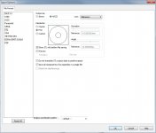
an STL version, and a screen shot of the STL settings.
I'm glad I've got Solid Works its much easier, I also use the IDF interface to get from the ECAD package (Cadstar) to the MCAD package (SW).
Glad to say I've developed a phobia for programming these days (as I've got older my patience has reached zero) the last I did being some Lisp for some Autocad routines.
Have Fun.
Attachments
hi marce,
Thanks again for your time. 🙂
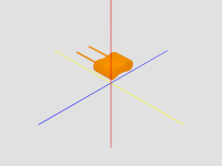
Converting the STL file to POV ended up being very simple and the result is shown in the attached image. The mesh file for this one object ended up being nearly 1 meg., at over 42,000 lines. 😕 Surprising... raytracing this file took only a couple of seconds.
regards
Thanks again for your time. 🙂
Converting the STL file to POV ended up being very simple and the result is shown in the attached image. The mesh file for this one object ended up being nearly 1 meg., at over 42,000 lines. 😕 Surprising... raytracing this file took only a couple of seconds.
regards
Attachments
- Status
- Not open for further replies.
- Home
- Design & Build
- Software Tools
- Eagle3D model for a Silver Mica cap