I've been working on a Dynaco Stereo 400, trying to get it back to life. One channel works fine, but the other is almost dead with only a very faint sound you can hear when you put your ear to the speaker. And the working channel has a very audible 120Hz buzz in the background.
I'm experienced repairing various things, but this one really has me scratching my head. I've tested about every possible component in it to check for failure and found everything fine. All the output transistors, fine. All the driver transistors, fine. Measured the idle current of the "dead" channel with an 8ohm load and was able to dial in 100mA, no problem. So, I'm thinking the problem must be from a failure of an AC component, since all the DC components seem to be doing their job just fine.
Already checked all the usual suspects: relay, fuses, connections, input coupling caps, power supply caps, etc... even have that entire input board (PC-29) completely out of the circuit and bypassed the relay, and no matter what I've tried, I've found no change in its condition. One channel works fine, and the other only has very quiet sound, no matter what I've done. I'd be tempted to throw it out a window at this point, but I wouldn't want to risk killing someone if it landed on them.
This amp was very badly damaged and repaired at one point in its life. Both the amp boards have burned spots where a handful of components were replaced by someone in the past. Naturally, I looked here first, but all the components and connections in the damaged areas check fine. Ironically, the worse looking of the two boards is the one that works just fine.
Very, very tempted to just gut it and rebuild something new in it with that huge transformer and heatsink. Any suggestions for something fun that runs on +/-75v?
I checked the main filters with and they checked mostly OK... one of the 10,000uF pair seemed a bit off - read a little low with fairly high ESR - but not anything so far off that would make me think, "this one is definitely bad". I plan to replace them anyway. But, I've been checking all the other electrolytics on the board too, and none have them have tested as failed outright. I will be replacing all of them, though. May as well anyway since they're so old. New ones should arrive Monday.
I've tested about every possible component in it to check for failure and found everything fine. All the output transistors, fine. All the driver transistors, fine. Measured the idle current of the "dead" channel with an 8ohm load and was able to dial in 100mA, no problem. So, I'm thinking the problem must be from a failure of an AC component, since all the DC components seem to be doing their job just fine.
Already checked all the usual suspects: relay, fuses, connections, input coupling caps, power supply caps, etc... even have that entire input board (PC-29) completely out of the circuit and bypassed the relay, and no matter what I've tried, I've found no change in its condition. One channel works fine, and the other only has very quiet sound, no matter what I've done.
Testing parts at random trying to find one out of spec is a a very slow, unreliable and messy way of trying to repair an amp.
An amp is not a box of parts (so far you've been treating it that way) but a *working* system, where those parts *interact*.
Start by posting the schematic for us to suggest what to measure or test .
Then you'll have to measure some voltages and feed it audio and see what the amp does with it.
The difference between what's to be expected and what's actually found will provide hints which will lead you to the actual failure.
Which by the way, may not be "a bad part" at all !!
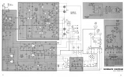
I agree about looking at it as a system, but the fact that I was able to bias it up as expected lead me to believe that part of it is OK. Here is the schematic, so maybe you can lead me in a better direction of where to look.
The parts that appear to have been previously damaged and repaired are R27, R31, R32, and R33. The replacements appear to be OK. These are components located on "PC 28".
The parts that appear to have been previously damaged and repaired are R27, R31, R32, and R33. The replacements appear to be OK. These are components located on "PC 28".
Attachments
Last edited:
Hi,
Did you check the speaker relay contacts? Also check the voltage at the fuse F301. It should be close to zero volts.
Did you check the speaker relay contacts? Also check the voltage at the fuse F301. It should be close to zero volts.
Hi,
Okay just forget about the relay contact. You mentioned that you bypassed it. Do you have a scope?
Okay just forget about the relay contact. You mentioned that you bypassed it. Do you have a scope?
I thoroughly cleaned the relay contacts and got them to measure a resistance of less than ,05ohm. I even bypassed the relay entirely just to be sure it wasn't a fault in it.
I was able to get DC voltage at the output of terminal 7 on the board (the point that connects to Fuse F301) to be about 70mV, depending on the setting of P1.
I was able to get DC voltage at the output of terminal 7 on the board (the point that connects to Fuse F301) to be about 70mV, depending on the setting of P1.
I do have a scope, I will pull it out tomorrow and start checking more in-depth. Any particular spots of interest you'd suggest? I guess I'll just start at the beginning and see where the signal stops...
Hi,
With a signal in I would check the bases of Q7 thru Q11. They are the pre drivers. Also you can compare the transistors voltages from the bad channel with the good channel. It will give an idea where it is the problem.
With a signal in I would check the bases of Q7 thru Q11. They are the pre drivers. Also you can compare the transistors voltages from the bad channel with the good channel. It will give an idea where it is the problem.
Hi,
I found this article about Dynaco 400 problems. Please check it out.
Link:Dynaco Repairs For PC-28 Amplifier Boards
I found this article about Dynaco 400 problems. Please check it out.
Link:Dynaco Repairs For PC-28 Amplifier Boards
Thanks for the schematic.
It's on the verge of readability; if you have another version at least 50% larger (or if you can re-scan it with higher definition) please post it ; if not we'll manage with this one, although maybe sometimes I'll enclose some number or label within ¿¿?? .
To begin from the beginning, please post DC voltage at:
Points # ... where I expect around
#7 ... < 100mV DC
#10 ... 1/2 what you get at #15
#15 ... +V rail ... maybe in the area of +60/70V , given the rated power
#8 ... 1/2 what you get at #4
#4 ... -V rail ... maybe in the area of -60/70V , given the rated power
Nets which in this case means copper joining 2 or more parts and the corresponding pads.
A net may have a lot of parts connected to it, but naming just 2 or 3 of them is usually enough for ID purposes.
A net may include parts in different PCBs or even connectors, jacks or switches which belong to none of them.
What defines a Net is being interconnected, which means you will measure same voltage or signal in any point of it.
So I want to know voltage at the following nets.
As before I hint at what I roughly expect .... but don't please me, post what you find 😉 .
Net R1/R2/Q1 (which is an elegant way to say "Q1 base") ... < +50mV
Net R9/Q2 ... similar to above, but may differ by, say, 20 mV, depending on transistor matching.
DC voltage on both sides of F301
DC voltage on both sides/contacts of Ry ¿¿3??01 or C308, which means the same.
DC voltage on J302
DC voltage on pins 5/6/R8 on board PC29
As you see, I didn't ask you to measure any part ... yet 😉
Good luck.
The fastest way to find a problem in a complex system is chop the problem in two by testing at a midpoint, then looking left or right as indicated. With a scope I'd put in an AC signal (I use a transistor radio) look at the collector of Q7 for signal. If the problem is before there, I'd next look at pin 1 of PC28 for signal coming in.
In the usual suspects category, C7 of PC28 and C1 the input cap are expired. Also the P3 level pot and the high-low filter bypass switches could be oxidized and not conducting. An eraser is nice if you can get it in there to the contacts, followed by alcohol, or spray cleaner and a lot of action if not.
These units were hand-built, either by a kit builder or at the factory, and any solder joints could have corroded off by now from unwashed solder flux. If you find a stage where the AC is disappearing, the usual DC rules about transistors apply. the voltage on one end of a path should be the same as at the other end ( the part legs, not the trace itself), Vbe =<.5v off and >.6 v on, Vce is lower than the part Vceo voltage (usually 40 except for output transistors.)
Last year one of these sold for $300 a couple of blocks from me unrestored, in a day or two on craigslist, so don't pitch it too soon. These are very well respected amps for home stereo use.
This page has links to hi-res versions of the schematic. Note that there are two different versions floating around, that differ mainly in some dynaguard and input details. This is discussed in the page also.
Stereo 400
Akitika GT-101 Audio Power Amplifier Kit
Stereo 400
Akitika GT-101 Audio Power Amplifier Kit
This page has links to hi-res versions of the schematic. Note that there are two different versions floating around, that differ mainly in some dynaguard and input details. This is discussed in the page also.
Stereo 400
Akitika GT-101 Audio Power Amplifier Kit
Ok, thanks. 🙂
Well, I just tried testing it some more. I went ahead and replaced R32 - the 750 ohm 2w - since that one article mentioned it as component that fails often and it was one of the few resistors in that part of the amp that hadn't already been replaced. I measured it, and it was about 810 ohm, which far enough away from its tolerance to make me think it was good to replace it. Also, I looked closely with a magnifier, and it did look like it may have a small crack in it, though it wasn't obvious enough to say for sure (I've seen cracked carbon comps before). I reinstalled the transistors I had removed to test, and double and triple-checked to make sure none of them were shorting against their heatsinks.
Plugged it in and flipped the switch. Within a second, the fuse for the negative supply to that channel blew in a flash of blue light. Checked for shorts everywhere I could think of and found nothing.
Thanks for the help up to this point, everyone. I guess now my goal is to find out why it's blowing that fuse. Perhaps I'll get lucky, and solving that problem will also solve the problem of it having no output.
Hi,
Did you check the R29 on the positive side? The article said that you need to replace 4 resistors R28 ,R29 ,R32 and R33.
Did you check the R29 on the positive side? The article said that you need to replace 4 resistors R28 ,R29 ,R32 and R33.
Sorry, I was incorrect. R29 is the one I replaced. R29, R32, and R33 had already been replaced previously by someone else. They were all replaced with modern types.
So now you have a problem you didn't have before, caused by your aimless messing with it.(describes replacing parts) .....
Plugged it in and flipped the switch. Within a second, the fuse for the negative supply to that channel blew in a flash of blue light. Checked for shorts everywhere I could think of and found nothing.
Perhaps I'll get lucky, and solving that problem will also solve the problem of it having no output.
No, it's another, different, new problem.
It didn't blow fuses before, and yet it already had no output.
Now you have two problems to solve, instead of one.
- Status
- Not open for further replies.
- Home
- Amplifiers
- Solid State
- Dynaco Stereo 400 Headache