Resurrecting a Stereo 120
Indianajo,
If you've been able to resurrect stereo 120's, then building and adding the bias controller should be a breeze for you. The parts are inexpensive.
The main thing about newer output transistors with more Hfe is that the current limiting circuit won't limit quite as early. The power supply, if still kind of stock, should mostly keep you out of trouble...However, if you don't have the fold-back limited power supply, the combination of no limiting in the power supply and less limiting in the amp could be deadly in a fault condition.
Good luck with your projects.
Dan
Watch out for!
C8 and R18...if either opens up, the amp won't be stable, although it may only show up when driven hard...the ultrasonic oscillation causes simultaneous conduction, and the amp eats itself. A sure hint is it R18 has burned open!
Also...the big 300 Ohm 5W (7W?) resistors often eventually open up...
C8 and R18...if either opens up, the amp won't be stable, although it may only show up when driven hard...the ultrasonic oscillation causes simultaneous conduction, and the amp eats itself. A sure hint is it R18 has burned open!
Also...the big 300 Ohm 5W (7W?) resistors often eventually open up...
runaway detector
I have checked my ST120, it is in fact drenched in cat hair and lint to validate the description of a previous poster. My C8 and R18 are fine, the 300 ohm 7 watt resistors are fine, the solid wire (yes virginia, they once made solid hookup wire) had come unsoldered from the top of the output cap (I didn't wrap it around or push it through) and sprung up in the air, causing the spectacular 18" fireball of vaporized lead. The NTE 60 output transistors (hfe <150) appear to be okay, the 1 ohm 10 W power resistors from the power supply to the transistor top are fine (instead of .5 ohm, my "improvement'.) So it didn't run away thermally this time.
I'm still scared of it. I would like to take the circuit proposed by kind and knowledgeable D Joffe, and make a thermal runaway protection device out of it, as well as a bias stabilizer. The writeup on the circuit diagram says that without r2, the new circuit produces 10 mv of bias, with the r2 at 33k the bias is 20 mv. I propose, version one, that we run wires out from the bottom of R2 to a fenwal microwave oven temperature snap action switch on top of a TO3 transistor that opens about 120 deg F. Assume the switch is isolated from the case. Then when the switch opens, a big pop occurs, and the amp sounds a little weird because the bias current is wimpy, instead of exploding verious resistors. Okay version 2, we put an inductor in series with the R2 and switch , with a capacitor to ground in parallel, to try to damp down the pop.
Version 3, we replace the fenwal snap action switch with a thermistor in series with a resistor to equal 33k. Unfortunately, the one I looked up, the GE Honeywell RL1006-11k-120-101, has a 25degC resistance of 20kohm, and a 60 deg C resistance of 19999.9999 ohm. But suppose I can buy one with a hot resistance of 40000 ohm - would this be cool as 20000 ohm of the 33kohm of R2? Would this also protect the amp from exploding resistors?
The reason I like the ST120 is, it only has 14 electrolytic caps, of which I have already replaced the 8 expensive ones. It sounded okay when working. The Sony TC 250 tape deck I was using to play LP's, that is now wimpy, has about 200 electrolytic caps, all of which need to be replaced. And it is only a 5 or 10 watt amp with 3" speakers. But the Sony doesn't catch fire.
If anybody wants to check my math, the thermistor mentioned has a t zero of 25 deg C (298 Kelvin) and a beta of 4356K. According to wikipedia, beta is the riciprocal of B, and Rhot=Rzero*exp(b*(1/t-1/tzero) all temperatures in kelvin, 25C=298 Kelvin. We used to use thermistors to heat up and stop the start motor current on refrigerator compressor motors, which they did fine, but those weighed about 2 oz and were not suitable for measuring temperature on to3 transistors.
djoffe bias board
Okay, no help from anybody on thermistors. I had to buy a couple to find out what they do. ( I did find a device textbook from the community college at goodwill for $2, very interesting all the new things invented since 1978). "100K" Thermistor at 60 deg room temperature, 140Kohm, between fingers 80Kohm, front of hair dryer 10Kohm. The equation for kappa on wikipedia apparently has nothing to do with the K that the thermistor vendors specify. That is backwards resistance change to put below the 33k resistor on Mr Joffe's bias board to cut bias back from 20 ma to 10 ma when heatsink is hot, per the notes on his drawing. So, I have bought some 2N7000's enhancement Mosfets, to put one between bottom of the R2 resistor mentioned and the 10 ohm resistor R25, to back off the bias current when the output heat sink is hot. I'm planning a resistor divider to control the mostfet gate, 100k from PC-14 pin 5 (the top of R2) to the gate of the 2n7000, the 100k thermistor between the gate and the top of R25 the 10 ohm resistor, and a 1 mf ceramic capacitor between the gate and the same top of R25, to prevent RF oscillation caused by proximity of the thermistor to the big output voltage swings on the heatsink, and any pop on the tweeters caused by the mosfet transistor shutting off. I'm a little worried about the 2n7000 gate voltage being limited to plus or minus 30 from the source, and also a little worried about the zener diode inside the 2n7000 between the drain and the source, but I'm hoping the whole voltage between PC14 pin 5 and the top of R25 floats around about +5 volts. The 2n7000 is guaranteed to turn on at 3 v gs, that was the lowest I could a buy. A depletion fet would be cooler, I could run the resistor divider down to power supply minus, but the only one I could find for sale IXPT1N also has a 20 volt limit GS, much less than the power supply excursion. I didn't use a junction transistor to shut off bias from R2 because I thought the VCE might be too high. Any comments on how obviously stupid this is are invited, with reasons.
I also do not understand how Q1 can be either a 2N3904 or a TIP31. I've got some of each, I'm building the board tonight. Newark calls the TIP31 a power darlington, and the VBE sat is about 1.8, whereas the 2N3904 is about .85V. So maybe Newark is right about darlingtonness. So I'm a little nervous about three diode drops instead of two in the base circuit of Q1 and Q2, since I really don't understand how this board works. Thanks for looking. The ST120 is playing away with the original two diode bias over in the corner, I'm not sure why it is so awful, but I've just come off listening to a clock radio for 2 years while everything real was broken, so a ST120 is a real improvement over that. It also sounds better than the IC stereo sound system in my 2007 model HD-TV.
Tip31
according to the data sheet, tip31 is a plain vanilla transistor, not a darlington...look at fairchild data sheet for the part, as one example.
according to the data sheet, tip31 is a plain vanilla transistor, not a darlington...look at fairchild data sheet for the part, as one example.
preliminary results
Okay, built one channel with 2n3904 for Q1 etc and additional 2n7000 between R2 and R25, the resistor that Mr Joffe says swings bias current from 10 ma to 20 ma. Works okay first shot, there is around 35 volts from Q5 collector to pin 7,8, plenty of headroom. With thermistor controlling FET gate at room temperature, R1 and R2 reading about 8 volts on DVM DC scale, also VGS on 2N7000 about 8 volts, it is on. With hair dryer on thermistor tied to gate of 2N7000, R2 voltage goes to zero and Vgs goes to less than 1VDC. Fet is off. Thermistor fits neatly in a #6 hole drilled in the heatsink attached to output transistors. Thermistor part number is 04T1003FF, Newak/Farnell PN 41K9381, NTC (negative temperature coeeficient), 100K nominal. Moving to "real" loudspeakers, Peavey T300's, for listening test. Bench Tested with a 8 ohm salvage car speaker on the new board channel, and 8 ohm 200W resistor on the two diode bias channel. No oscillation apparent on scope wherever thermistor leads is, including stuck in hole in TO220 heat sink screwed on top of Q5 case. 1uf is on gate to source. Thermistor leads about 6", other leads to board about 4". 1 1/2" x 3 1/2" perfboard mounted flush with top of PC14 on sheet Metal angle screwed to mount for PC 14. Construction point to point solder & wires. Thanks Mr. Joffe.
Okay, built one channel with 2n3904 for Q1 etc and additional 2n7000 between R2 and R25, the resistor that Mr Joffe says swings bias current from 10 ma to 20 ma. Works okay first shot, there is around 35 volts from Q5 collector to pin 7,8, plenty of headroom. With thermistor controlling FET gate at room temperature, R1 and R2 reading about 8 volts on DVM DC scale, also VGS on 2N7000 about 8 volts, it is on. With hair dryer on thermistor tied to gate of 2N7000, R2 voltage goes to zero and Vgs goes to less than 1VDC. Fet is off. Thermistor fits neatly in a #6 hole drilled in the heatsink attached to output transistors. Thermistor part number is 04T1003FF, Newak/Farnell PN 41K9381, NTC (negative temperature coeeficient), 100K nominal. Moving to "real" loudspeakers, Peavey T300's, for listening test. Bench Tested with a 8 ohm salvage car speaker on the new board channel, and 8 ohm 200W resistor on the two diode bias channel. No oscillation apparent on scope wherever thermistor leads is, including stuck in hole in TO220 heat sink screwed on top of Q5 case. 1uf is on gate to source. Thermistor leads about 6", other leads to board about 4". 1 1/2" x 3 1/2" perfboard mounted flush with top of PC14 on sheet Metal angle screwed to mount for PC 14. Construction point to point solder & wires. Thanks Mr. Joffe.
Congrats...
Two questions:
Can you post some pics?
What was the idling current you had...E.g., how many millivolts across the 0.47 Ohm resistor?
Two questions:
Can you post some pics?
What was the idling current you had...E.g., how many millivolts across the 0.47 Ohm resistor?
Joffe Bias circuit ST120
Okay, ST 120 idling current of R27 after 8 hours turned on with a fan on it. Sear Craftsman meter. Joffe circuit side, 21.9 mv. Two diode side, 1.0 mv. Heat sinks pretty cold, I had the fan I bought on it. When cold at 1500 I tried a Joe Jackson LP, he must have a synthesized piano, I couldn't hear the difference. On the FM radio playing Chopin at 1900, I couldn't hear the difference. Finally, tonight after 8 hours, I put on a Peter Nero RCA Victor LP, where he plays a grand piano, sometimes totally alone. The Joffe side sounds a little better if I put my ear in front of the tweeter, especially when he plays on the topmost octave. I have a Steinway console between the two speakers, neither speaker sounds as good as the real piano. I swapped the outputs of the preamp to see if that was the difference, it is a Herald Mixer I got for $15 and I think there is something wrong inside because it plays fake stereo(some instruments on one channel, others on the other) totally differently depending on which was the phono inputs are put in. There is no mono setting or AB, and my PAS2 has a bad volume control and hasn't been turned on in 12 years. . The Joffe side sounds better on the solo top octave piano with either channel of the preamp driving. Cymbal, another hard to reproduce thing, I can't tell the difference. Even unmodified the St120 sounds better than that 4 driver/speaker monstrosity of a stereo system they have playing on the sidewalk of the RAC rental center.
One difference between this ST120 and the one in the model, the model has 2N3772's as output transistors and TIP31 and TIP32 as drivers. This unit has NTE60's output transistors on the Joffe side (hfe <150) and NTE181's on the 2 diode bias side. The drivers on the Joffe side are TO5 cans with 5 digit RCA numbers on them. The drivers on the 2 diode side are NTE49 and RCA SK3441, high gain 100v TO220 transistors. This product was apparently built about '72 after all the reviews were written and filed, and the price of transistors quartered. When I bought it blown up it had 2N3055 output transistors. I don't know if the extra gain of the modern transistors is why I don't find the ST120 so awful sounding after putting away a ST70 because the tubes were too expensive to replace.
I don't have any way to take macro lens pictures. If you PM your address, I'll mail you the 2nd board after I build it before installing, to be mailed back, if you wish. I did do extensive work on the Power Supply foldback circuit on this unit, When I repaired it blown up in 1984 I put a NTE 60 for the TO3 PS transistor, and R23, which was incinerated with the NPN driver, to 5600 ohms. No schematic. This made the foldback circuit trip at 2.4 amps, tested last month. Putting R23 back to 1000 ohms put the foldback to 5 amps. Putting a really old rusty RCA TO3 transistor on got it up to folding back at 7 amps. Thanks for posting this circuit.
hardening circuit
Okay, the second Joffe board was built, produced 470mv of bias current (900ma) due to heat sink grease being on the threads of the Q6 collector screw, which insulated R27 from actually connecting to the transistor collector. Odd, the amplifier sounded good on both channels (the bad one with double diode bias) the night before the mod, as I said some slight improved accuracy on high frequency of piano on the Joffe circuit side. The ST120 is really designed for idiots to build poorly and still please. When I installed the second Joffe board, the ring terminal to Q6 screw produced a welding spark as it tried to connect: then it blew the transistors Q8 and Q9 on the Joffe board, causing the 900 ma bias. The destroyed Q8 was biasing Q10 to .75 v on BE junction, dumping all that current. The correct board was reading .45 v Vbe, with a cold bias of 27 mv and hot about 22 mv. The 2N7002 did not go out, protected by its internal zener diode. Which brings me back to using 40v Vcbo rated 2N3904 transistors in a circuit with 72v (correct) 100 v (possible) rails. Good as long as nothing goes wrong. 2N3904's are cheaper than fuses, 10 cents instead of 66, that is the only good thing. Per Mr Joffe's statement that 300 MHz frequency rating is important, I have found some Zetex ZTX653 signal NPN transistors for $1 that are actually rated for 100 Vcbo. Their frequency is 175 MHz, not as good as a 2N3904, better than a 3 Mhz rated TIP41 Mr Joffe said was unacceptable. This circuit does follow half the music signal on the o-scope. With new 2n3904's and continuity to Q6 collector repaired,, voltage across R27 is running 35 VDC, diagnosis is suspended until UPS runs from S Carolina to Indiana with 100v transistors. I don't have 40 v zeners either. A 200 ma fuse Joffe board to PC14 pin 7 or 8 might be a good idea too, Q5 got pretty warm in a couple of minutes.
One additional way to bullet proof the ST120, it pops naturally into the speaker as it is turned off due to transformer field collapse. I put a terminal strip over near the (much smaller) PS cap and soldered a short lead blue UL rated snubber (disc) across (electrically) bottom terminals of the power switch. No more pop, and some possible lightning protection too if you put another one from neutral to case, and you've grounded the case somehow. (my safety ground is in the preamp, through the RCA cable shields, not safe enough yet, but correct signal star return wise). The snubber was salvaged from a switching power supply for PC's. Make sure it has the rating agency logo appropriate to your country, for installation across the mains.
Last edited:
100 v transistors vs amateur construction
This is one of the top ten Dynaco Stereo 120 responses that come up on the search engines, so I will post my final results for amateurs like me although the pros on this site may still disrespect the ST-120. The two DJoffe designed boards constructed by me are installed, the avalanched 2N3904's on one channel destroyed by a little heat sink grease on the collector screw attaching R27 to Q6 were replaced. It sounds good. The 100 Vceo rated ZTX653 transistors arrived and were installed for Q8 and Q9 on one channel instead of 60 V rated 2N3904's. The ZTX653s doesn't sound any different from the 2N2904s on the other channel, despite being rated at 140 MHz Ft instead of 300 Mhz. R27 voltage is still 22 mv, just fine at Mr Joffe's intended 40 ma bias current.
At bit of circuit description of Mr Joffe's bias design, for those of you like me that don't find everything inherently obvious. The original 2 diode and a capacitor Dynaco bias circuit was actually producing 4 mv on R27 quiet, and 10-15 mv with music playing. Apparently the diodes rectify the AC signal into the capacitor, to produce bias current and eliminate the turn on notch voltage. That is why Mr Joffe said playing ST120's softly produced pain in the ears. I never heard it, because if I want soft whistle music I turn WUOL-FM on the clock radio- I mostly played the ST120 at a 2v output volume.
On Mr Joffe's circuit, Q9 measures the difference between the 40 VAC signal at the bottom of Q5 the top output transistor, and the 40 VAC signal at the top of Q6, the bottom output transistor. Q8 compares this voltage against the 33k resistor, and if it sees the differential volage (which is the current across R27, the 1/2 ohm resistor the bias current flows through) as too low, it pinches down Q10, allowing more current from R3 to turn on Q2 and Q1, pumping more current out the pin 7 or 8 lead. The avalanched (shorted across C-E) Q8 2N3904 was allowing Q10 .7 V across Vbe, which was pumping 280 mv across R27 between the transistors. No transistors of the original Dynaco boards were avalanched or open, I checked them all by lifting the base lead and the double diode test. Proper Q8 action puts about 0.4 Vdc across Q10 b-e, for linear regulation. As Q1, Q2 and Q10 don't see very much voltage routinely, I did not replace the $.025 2N3904's there with $1.10 ZTX653s. As amateur fumbling can easily put more than 60 V across Q9 and Q8, I recommend the ZTX653's there, or at least $.0025 MPS8099's rated Vceo of 80v. All bias currents I measure were with an averaging DVM that integrates over about 3 seconds. As far as calibration goes, this meter was measuring forward dc biased silicon diodes at about 650 mv.
The thermistors I added are tied to the fins of TO220 transistor heat sinks added on top of the Q5s. When I heat them up with a hair dryer(in the air), the cutoff of R2 by the fet is cutting the bias current to 11 ma. Mr Joffe's original circuit tended to pinch more as the transistors got hotter, but this halves the bias current if anything is warm.
I managed to break the wire to the base of Q5 while I was fumbling around checking transistors, which caused the power board to foldback to 15 VDC, and the TO3 Q9 on it to get really hot really fast. I like having foldback to save $10 apiece output transistors, so I don't like Mr Reaton's 70V at all times power circuit. However, the heat sinking on the Dynaco is not good enough to really protect anything. I've got some more thermistors and a sack of 100V signal transistors. Stay tuned to this thread for a latch circuit add on to the power board to detect heat, shut off power to Q9 and the output capacitor, latch on, and light a diagnostic LED. I think it will take 2 transistors, on of them a big honking FET salvaged from a switching PC power supply.
Last edited:
update- heat and reliability
Okay, this is the main ST120 thread, so I will continue for the other person out there interested. I hadn't been using the St120 because one of the 44 year old RCA jacks was ittermittant, and I didn't fancy drilling to put in the gold plated plastic shell pair I bought. I recently bought a ST70 input jack pair on a phenolic board from triodeelectronics.com, I think, and sawed it in two, and notched the top and bottom ground flanges with a needle file, and got it wedged in the original hole with the two 4-40 screws and grounding washers. Eureka!. Have used it all week, sounds fine.
Hung the two 1.5"x2.5" Djoffe bias boards from angle brackets and standoffs from the top angle sink-PC15 screw, over top of the new reduced size output caps. So I could wedge the grill back on. Finally, hasn't been on in 10 years. Wouldn't fit over one of the TO220 heatsinks attached to the top of the TO3 NTE60 transistors, so I got a smaller one on. The TO220 heat sink is a candle in the dark night, anyway.
Been running the CS880s all day with the FM radio on, so I tried the same with the ST120, with the addition of a 6" plastic fan blowing across from right channel to left.
Okay, today I'm ready to try the repaired CS800S again, so after 12 hours on (at 1vPP out average) I took the cover off. The right channel facing the fan is fine, the left channel away from the fan is hotter than I can touch- heat sink, transistor, flange, all of it.
More thermal management is in order. This is the unit that set fire to the carbon resistors to the output transistor after a 4 hour rehearsal (and probably 3v PP out) after all. I've got these salvage heatsinks 6"x4"x1" thick, but can't figure any way to fit them in. Plus drilling them to fit TO3 would be tricky, they are undrilled. Right now I'm thinking putting two 12V computer fans under the holes in the bottom below the output transistors, and a little transformer, rectifier, fuse, etc in a little mesh enclosure to be screwed under the main ST120 body. It's a shame they don't make tiny 120 VAC fans- all the surplus ones I have are 12 VDC or 5VDC.
Stay tuned for the further adventures.
You know that the input capacitor C1 is tantalum and likely has dielectric absorption of 3 percent. Nobody tolerates distortion at 3 percent. However if we replace this with a 5 uf polypropylene capacitor it gets rid of the harsh metallic sound. After the Stereo 120 warms up sufficiently it really really sounds good. I have the Stereo 120 with the latest circuitry which likely adds stability, so I do not want to modify it very much. Just thought I would add the polypropylene capacitor, and you can also bypass the output capacitor with a 5 uf polypropylene to again decrease the dielectric absorption. These were well described by Walt Jung in his 1980 Audio articles. 🙂
Stereo 120 sounds great
Noted that the bias is about 20ma when playing music at a moderate level. The Pioneer SX636 has about the same bias and sounds nice. However when I first turned on the amp it sounded very metallic and bad. I noted that the dual diode bias takes some of the output and turns it into DC bias.
You know that the input capacitor C1 is tantalum and likely has dielectric absorption of 3 percent. Nobody tolerates distortion at 3 percent. However if we replace this with a 5 uf polypropylene capacitor it gets rid of the harsh metallic sound. After the Stereo 120 warms up sufficiently it really really sounds good. I have the Stereo 120 with the latest circuitry which likely adds stability, so I do not want to modify it very much. Just thought I would add the polypropylene capacitor, and you can also bypass the output capacitor with a 5 uf polypropylene to again decrease the dielectric absorption. These were well described by Walt Jung in his 1980 Audio articles. 🙂
Noted that the bias is about 20ma when playing music at a moderate level. The Pioneer SX636 has about the same bias and sounds nice. However when I first turned on the amp it sounded very metallic and bad. I noted that the dual diode bias takes some of the output and turns it into DC bias.
Hello, Im new here but I need some help. I picked up a used Dynaco 120 and hooked it up to my JBL studio monitors and it sounds distorted. Kinda bad...
Is there something i can replace to give it a semi quick fix?
thanks,mike
Is there something i can replace to give it a semi quick fix?
thanks,mike
This link has a lot of good information:
Dynaco Stereo 120 Repair
First things to check...voltage across C12...should be 72 Volts.
Voltage on positive terminal of C7 (both) should be about 36 volts.
If both are far wrong, then you've got a good place to start.
Dynaco Stereo 120 Repair
First things to check...voltage across C12...should be 72 Volts.
Voltage on positive terminal of C7 (both) should be about 36 volts.
If both are far wrong, then you've got a good place to start.
Hi,
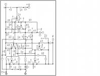
Just in case that it may help any one fixing Dynaco 120 amplifiers attached it is the schematic of the Dynaco 120 driver board showing all the reading voltages from a good working amplifier. Also for you information you can replace the 2N3055 with the 2N3442G transistor. It is a 140 volts and the sound it is as good or better than the original 2N3055. Hoped this information can be useful for those repairing Dynaco 120 amplifiers.
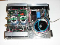
Also attached it is one of my Dynaco 120 rebuilt.
Just in case that it may help any one fixing Dynaco 120 amplifiers attached it is the schematic of the Dynaco 120 driver board showing all the reading voltages from a good working amplifier. Also for you information you can replace the 2N3055 with the 2N3442G transistor. It is a 140 volts and the sound it is as good or better than the original 2N3055. Hoped this information can be useful for those repairing Dynaco 120 amplifiers.
Also attached it is one of my Dynaco 120 rebuilt.
Attachments
45 year old electrolytic capacitors are a pretty sure shot to be bad, including the tantalums on the input as previously said. I bought *****y new 4.7 uf tantalum caps in 1989 that made popcorn noise, and ended up in 2011 using 4.7 uf aerovox gold ceramic caps for the input. Much better. Note these are 50 v ceramic caps, which straigtens out the curvy ceramic capacitance curve on a 1.6 vac signal. New electrolytic caps like snap in case caps for the 3300 ones will be much smaller, will need to be stuck in with glue because they don't fit the clamps. The C11 500 mf (470 uf these days) can be hung off the board they are so small.Hello, Im new here but I need some help. I picked up a used Dynaco 120 and hooked it up to my JBL studio monitors and it sounds distorted. Kinda bad...
Is there something i can replace to give it a semi quick fix?
thanks,mike
The 2n3055 output transistors if original, will have five digit numbers from RCA on them instead of 2n3055- I have one left on the power regulator board. upgrading to faster modern transistors is not a major change, it just cleans up the high frequencies a little. A major heat tolerance improvement is the On semi MJ15015 which I picked up for $1.60 each. If installing faster modern transistors do the TIP mod detailed on greg Dunn's dynaco website. To prevent oscillation of faster output transistors there needs to be a zobel network on the output, also 47 pf ceramic driver transistor capacitors to short out ultrasonic oscillations.
Really bad sound also might be a bad solder joint (these were amateur assembled mostly) or a shorted OT, check the transistors out of circuit with a diode check on a dvm, 450-600 ohms (millivolts) forward on both junctions, 1999 mv (ohms) backwards.
I did my fan addition mod I ruminated about above, putting two PCAT fans around the heat sinks outside the cover, with an external 9v wall transformer as power, which saved the bacon when the closed loop bias board covered in the earlier posts went open loop due to unmatching of the gain over time of the input transistors. After 14 months use I found the output transistors suffering from 250 ma of bias current on one channel, which they were tolerating because of the fans and sounded good, but is not a good practice. Djoffe's akiko board to put a LM3886 IC instead of the PC15 and output transistore probably works okay but limits the headroom on the output IMHO more than the modern transistors which can get output of 35-40 VAC for brief musical peaks.
I've lost two transistors in the sense position of the closed loop bias board I built to the design shown earlier. Both were 2n3904, the first because I had heat sink grease on the collector connection to the Q6 put 72 v on the Vce, the second for mysterious reasons after 14 months, possibly SOA violation. The second transistor was not blown, just it wouldn't make the current mirror work anymore to shut down the OT bias current if too high. The channel with the closed loop board using $1 each ZTX653 sense transistors is still working fine. I'm trying to build a more conventional potentiometer controlled bias driver board a la pwg tang, but there are issues with new >400 gain transistors, I'm reporting results in this thread http://www.diyaudio.com/forums/solid-state/53053-dynaco-st-120-a.html
If one is willing to go all the way to buy a 80 v Vceo pnp input transistor, which I didn't have when I started this latest driver board, the Apex 6 could be used as a driver board if wires are run out from his PC board to the TO3 transistors on the heat sink of the ST120- http://www.diyaudio.com/forums/solid-state/236256-retro-amp-50w-single-supply-19.html
Of course if one were going to buy new transistors, one could buy plastic cased ones and just build the board as is, using the ST120 case and transformer. I'd keep the PC14 voltage regulator board, regulating the supply to 72 vdc and current out to 6.25 a is a good idea. I have a 10 amp fuse on my dc current out of the C12 3300 uf cap, also. I haven't toasted any output transistors however since 1990, when a wire melted off the output capacitor, sprung up and touched the case top, and blew the OT's. Lesson learned, install fans, the whole chassis was the temperature of melting solder after 4 hours of PA use in a choir rehearsal.
Have fun.
Last edited:
- Status
- Not open for further replies.
- Home
- Amplifiers
- Solid State
- Dynaco Stereo 120...can be beautiful