Hi, if you are build your own Dynaco, I wish I can get some info from you, because I am thinking of build 1 for my own. I need some experience expert for guides.
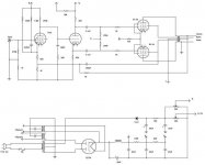
I got the original Dynaco ST70 schematic with me (shown below). With the following tube I could able to start my construction.
4 x E34L quad matched
2 x 7199
1 x GZ34
I got the original Dynaco ST70 schematic with me (shown below). With the following tube I could able to start my construction.
4 x E34L quad matched
2 x 7199
1 x GZ34
Attachments
7199s were difficult to source last time I checked. Have you located some? What transformers are you planning to use?
Replace the 7199 tubes with 6U8's. Performance will be the same. Be aware that the pinout is slightly different.
In the 2nd circuit, I'm somewhat dubious about a 12AU7, with it's mu of 20 having enough gain, especially since there is degeneration in the O/P stage due to the unbypassed cathode resistor.
In general, I LIKE the 2nd circuit. I would quibble with the details. The reality of tubes not being TIGHTLY matched can't be ignored. "Fixed" bias with individual adj. pots. for each tube allows exact setting of idle currents, which compensates for mediocre matching. I would use a tube with more gain than the 12AU7, say the 12AT7 and instead of grounding the non-inverting triode's grid, use it as the point of application of negative feedback picked up from the O/P transformer's secondary.
In general, I LIKE the 2nd circuit. I would quibble with the details. The reality of tubes not being TIGHTLY matched can't be ignored. "Fixed" bias with individual adj. pots. for each tube allows exact setting of idle currents, which compensates for mediocre matching. I would use a tube with more gain than the 12AU7, say the 12AT7 and instead of grounding the non-inverting triode's grid, use it as the point of application of negative feedback picked up from the O/P transformer's secondary.
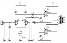
Something like this?
Still subject to tweaks but a prototype is up and running just fine.
An externally hosted image should be here but it was not working when we last tested it.
Still subject to tweaks but a prototype is up and running just fine.
Jax,
That's impressive! There's very little I would change. Use the less expensive, but EQUIVALENT Locktal 7N7 instead of the 6SN7. Change the EL34 cathode resistors to 100 Ohms, for a "dose" of Dennis Boyle's combination bias.
FWIW, I had a 2 stage circuit with a 12AT7 as the phase splitter in mind using a less sophisticated CCS (an enhancement MOSFET).
Frank Berry said:7199 tubes with 6U8's.
I've a whack of used 7199s -- even a couple cryoed new ones i'll never use... even more 6U8s.
This is the direction i'm going with my ST70 (compliments of Allen Wright):
An externally hosted image should be here but it was not working when we last tested it.
I may well use 6H30Pi or ECC99 (althou with 6H23Pis on hand...)
dave
Thanks, Eli.
One of my goals in the design was to reduce the number of low frequency poles within the loop to a reasonable minimum. There are only two left, the coupling caps and the transformer. Differential stages is a good way to avoid decoupling caps combined with the DC-coupling.
I have been thinking of stabilizing the output stage bias with higher cathode resistors but 100 ohms? Should they be decoupled? You made me curious now 😀
SY said:p10- all you need is a Jensen JT11-P1 on the input...
or get the balanced pre out the gate (have a significant portion of the kit already, and the rest is mostly paid for)
dave
Combination bias attempts to have "EVERYTHING". The unbypassed 100 Ohm cathode resistor provides: some of the grid bias needed, stabilization of the operating point, and reduced distortion due to degeneration. TANSTAFL does apply, as the O/P impedance is raised slightly.
Hi,
Why the extra xformer?
You can easily ignore it, the Boyle idea also provides for some extra safety to the output tubes in case the bias supply goes on the blink.
Needless to say...I like it.😉
p10- all you need is a Jensen JT11-P1 on the input...
Why the extra xformer?
as the O/P impedance is raised slightly.
You can easily ignore it, the Boyle idea also provides for some extra safety to the output tubes in case the bias supply goes on the blink.
Needless to say...I like it.😉
Why the extra xformer?
Balance and galvanic isolation. Steve Eddy has brainwashed me.
- Status
- Not open for further replies.
- Home
- Amplifiers
- Tubes / Valves
- Dynaco ST70