Help needed!
I am trying to restore an ancient Dynaco ST120 and it actually amplifies and it puts out the power it is supposed to, but it draws way too much ilde current. One channel draws a little more than 1A and the other slightly less than 2Amps. There is no high frequency oscillation (if there is it is below 120MHz)!
For an amplifier that boast no quiescent current this seems a bit too much. So there must be a fault somewhere - but I simply can't find it. The transistors check within the specified specifications, the resistors too and I have changed the diodes and changed/checked the electrolytics. But obviously, there's something I have overlooked - does anybody have an idea where to look and/or how to overcome the problem?
Attachments
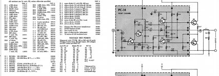
Have a read--clear /good schematic each section described -
Microsoft Word - Analyzing the Dynaco Stereo 120 Power Amplifier.doc - OriginalAmpModuleAnalysis.pdf
Microsoft Word - Analyzing the Dynaco Stereo 120 Power Amplifier.doc - OriginalAmpModuleAnalysis.pdf
I'd check D1, D2, D3, or D4. Also C6 is involved in the bias circuit, which needs changing if it is 50 years old.
Actually it probably sounds much better at 1 A idle current versus OEM. The reviews trashed these things in 1966 because at low output wattage cold, there was too little idle bias and much crossover distortion. 6CA7 ST70 sounded much better in 1966.
This thread tells how to modify them by adding 7 transistors etc to fix the idle bias at 20 ma with a closed loop system monitoring R27.
Dynaco Stereo 120...can be beautiful - diyAudio
I did that. However it blew the sense transistor twice which crams the idle bias up to 220 ma. May violate soa rating (not specified) of 2n3904. I had a little better luck with a diodesinc ztx653.
Because I could never buy TO5 drivers (until this year) my PC15 on one channel got lands torn off trying to fit in TO220 parts. So I built an apex AX6 point to point. The stock AX6 pcb is too tall for the ST120 chassis. My board was 3.5"x5.25". Retro Amp 50W Single Supply - Page 22 - diyAudio
Sounds just as good as PC15, with MJE15028/29 as drivers and 30 mhz GE D44R4 as VAS. My surviving PC15 has original RCA drivers & vAS, probably 50 mhz 2n5320/22. (house numbered).
Note also somebody that simmed the circuit on here found changing from 400 khz 2n3773 (1970) to 4 mhz tip3055 really cut the high frequency intermodulation distortion. I can't do a hearing test on that, all the 1970 transistors were blown when I bought my unit. I'm using NTE181mp output transistors which is probably MJ15003 in a white box (same soa rating). However do the TIP mod which puts the zobel on the back of the output jacks.
If you don't know what the tip mod is, see the greg dunn website.
With B+ regulated to 70 v now instead of that PC14 kluge (5 parallel TIP142 with emitter resistors) my unit will put out 70 v/ch for 5 seconds, measured. With a modern transistor instead of the dynakit gain selected 1970 one, PC14 was collapsing rail voltage at 1.5 A instead of the 6.75 amp specified. I replaced the current sense function of PC14 with a 10 A fuse.
The djoffe mod PC15 and the AX6 sound just as good at 1/4 to 70 W as my Peavey CS800s which has no capacitors on input or output. That is a .03% HD amp. That is using Peavey SP2-XT speakers on Steinway grand piano source tracks, which is a very difficult test for sound accuracy.
Note I put dual PCAT fans blowing on the output transistor flanges, because these things blew up output transistors so often. Not enough heat sink IMHO. I also added a flat fin TO3 heat sink to each flange, but it wouldn't fit under the TO3 transistors. Fans run at 9 v instead of 12 for quiet, but I installed the amp behind a 300 lb Hammond organ so I can't hear the fans.
Happy repairing & modifying.
Last edited:

- Home
- Amplifiers
- Solid State
- Dynaco st120