I'm working on this Dynaco ST-120. All capacitors have been replaced. Sound is okay, but one channel is 10WPC short. Upon investigating, I discovered some voltages are off in the input stage. However I can't figure out why and I've ruled everything out.
All resistors measure in spec. I replaced a few too while investigating too.
I tried swapping out Q1 and Q2 for new replacements.
I checked my solder work. No loose connections or bridged joints.
They are powered by the same supply voltages.
Collector of Q2 has about 5 extra volts on it.
Here's some voltages.
Bad side [Good Side]
Q2: (ECB) 3.3 42 3.9 [3.9 37 4.5]
Q1: 1.41. 3.9 2 [1.29 4.4 2]
R3, 1k: 12V [14V]
R7 1.5k, 17.8 [21]
Voltages on the output side all seem the same. Within 500 or so mV. Negative side of C3 and C4 are the same in both channels.
This should be easy but I've seemingly ruled every possibility out and don't know what else could be going on. Could the circuit just need an adjustment?
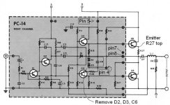
Ignore the notes on the schematic, they are for a bias circuit addition I haven't had to do.
All resistors measure in spec. I replaced a few too while investigating too.
I tried swapping out Q1 and Q2 for new replacements.
I checked my solder work. No loose connections or bridged joints.
They are powered by the same supply voltages.
Collector of Q2 has about 5 extra volts on it.
Here's some voltages.
Bad side [Good Side]
Q2: (ECB) 3.3 42 3.9 [3.9 37 4.5]
Q1: 1.41. 3.9 2 [1.29 4.4 2]
R3, 1k: 12V [14V]
R7 1.5k, 17.8 [21]
Voltages on the output side all seem the same. Within 500 or so mV. Negative side of C3 and C4 are the same in both channels.
This should be easy but I've seemingly ruled every possibility out and don't know what else could be going on. Could the circuit just need an adjustment?
Ignore the notes on the schematic, they are for a bias circuit addition I haven't had to do.
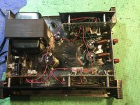
Attachments
with a dummy load of 8 ohms, you can monitor on the scope output voltage swing with a 1khz input..
this is the sure way of checking...maximum output swing happens when the output node is around 1/2 B+, but not exactly so, around that level is about right, the lower power trannie will have more voltage loss...
this is the sure way of checking...maximum output swing happens when the output node is around 1/2 B+, but not exactly so, around that level is about right, the lower power trannie will have more voltage loss...
Yes, pulled one leg on all resistors in that part of the circuit. Checked the rest of the resistors too.
I replaced the output inductors creating by wrapping the wire around the original output caps with actual inductors. 10uH. Found a schematic with that value on this site somewhere.
I replaced the output inductors creating by wrapping the wire around the original output caps with actual inductors. 10uH. Found a schematic with that value on this site somewhere.
Attachments
There is a feedback loop C13 and a clamp capacitor C15. Suggest you check those capacitances then look at AC volts there with standard input. Too much feedback cuts gain, C15 could swallow output. These parts can be ~58 years old. disk caps are usually reliable but 58 years is a long time.
These can be amateur built. Wash any flux off the board in the input area with 70% alcohol. Current leakage can leak away the gain. These are paper boards; burns can contain carbon which is leaky.
These can be amateur built. Wash any flux off the board in the input area with 70% alcohol. Current leakage can leak away the gain. These are paper boards; burns can contain carbon which is leaky.
Last edited:
I agree a scope is the instrument of choice to find the problem.
I suspect that the higher Q2 collector voltage on the defective channel is not the problem. The Q2 collector is bootstrapped by C3 and I believe its bias voltage is relatively uncritical.
Use your scope to look at clipping behavior, especially at the driver stage Q2, using the good channel for reference. Does the Q2 collector clip symmetrically, again comparing with good channel? I would look at C5 to confirm good AC bypassing of R8 that could compromise drive amplitude. Also use scope to look for AC loss across C3, C4, C7.
Signal does indeed clip at Q2 collector at same point it clips in the output. And in both places, as soon as it clips, the point of clipping gets pushed down more. For the top of the wave. If that makes sense.I agree a scope is the instrument of choice to find the problem.
I suspect that the higher Q2 collector voltage on the defective channel is not the problem. The Q2 collector is bootstrapped by C3 and I believe its bias voltage is relatively uncritical.
Use your scope to look at clipping behaviour, especially at the driver stage Q2, using the good channel for reference. Does the Q2 collector clip symmetrically, again comparing with good channel? I would look at C5 to confirm good AC bypassing of R8 that could compromise drive amplitude. Also use scope to look for AC loss across C3, C4, C7.
The other channel clips on the bottom first. But it meets spec.
No loss across any of these caps. And they are all new.
Heat sink limited ST120 to 60 w/ch, for 1 hour only. Improve the heat sink, and MJ15003 or later output transistors, it is a 75 w/ch amp 8 ohms (5 seconds my measurement). updatemydynaco is a 38 w/ch 8 ohms amp (LM3886). I use the Apex AX6 driver board, same remote output transistors, same single 3300 uf rail cap. Fewer parts.A) Rebuild it with Updatemydynaco.com guts ( cheapish and sounds a whole world better)
OP, remember Q1 was a special high gain transistor to maintain compatibility with the dynaco PAS1/2/3 preamps. I found MPS8099 I bought a roll of were ~300 gain, but average replacement transistor you installed may be more like 25.
I modified AX6 resistors to have the high gain to fit my PAS2 preamp.
Last edited:
- Home
- Amplifiers
- Solid State
- Dynaco ST120 weird issue