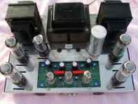
I finished my ST-70 about 3 weeks ago and I'm extatic. It sounds absolutely heart-warming. The only mod I made was to replace the p/s cap and a couple of the electrolyitcs under the chassis.
Now, I'd like to install dual dpdt switches to switch from pentode to triode mode. Does anyone have any suggestions for some nice switches? I'm not sure how much voltage is coming from the feedback loops on the trannies, so I thought it would be best just to ask...
I'll post pictures when I get home tonight...
Brian
Now, I'd like to install dual dpdt switches to switch from pentode to triode mode.
This was how I did it on my first Dynaco Stereo 70. Its a quad pole double throw switch. Its not rated for the voltage it sees but I never had a problem with it. I also never switched it on the fly. I switched to triode mode before turning it on.
Since I have experienced the triode mode on the stereo 70 my personal comment it that I don't see anything particularly special about the amp in triode mode. Maybe that is something that I need to look at again in one of the amps I have now.
Attachments
On some other forums, I have seen the following recommendations -
Shin Chin p/n R13-25B1-05 (Mouser 112-R13-25B1), rated 6A @ 250VAC.
Radio Shack # 275-636
While you are doing this mod, it may be a good idea to put the 100 ohm, 2W
resistor right at the tube socket on pin 4 so that it is always connected in both UL
and triode mode.
This was recommended on the diytube list to help prevent tube arcing/flashovers.
While this may be an issue seen more with SS rectification and newly manufactured
tubes, it does not hurt to have it.
I made this change recently, and I do not observe any change in the sound,
but then I have not been blessed with magic ears.
More info here -
http://www.audioxpress.com/magsdirx/ax/addenda/media/Gillespie2544.pdf
The switch that I used was also rated 6A/250 volt. While it worked ok I still recommend that it never be flipped while the amplifier is on.
Thanks for the quick response although it took me a few days to get back in the swing of things again. QT, just for clarification sakes, did you mean to place the 100 ohm resistors on lug 4 in series with the feedback leads from the trannies?
I read the article you recommended, and I hate to mis-read anything. I understand about the stabilization of the tubes, but the arc thing (as a whole) was a little new until I read the article.
Before attempting the conversion, I thought I'd try just to hardwire it over to Triode mode for a while. Boy, did THAT open a can of worms. At first, I noticed a significant difference in the midrange and presence. With a smile on my face I walked away to answer a beckonning call. When I returned, the right front tube was glowing brightly! I unpugged it as fast as I could (there's a lot to be said for a front-mounted power switch).
It took me a while of investigation, but I never actually did identify the culprit. I cleaned the 10K bias pots and resoldered a good deal of the PC-3 just be on the safe side, and I swapped the EL-34s to see if the problem followed the tube. It turned out that the right front position was the only one affected, but I'm a little leery about leaving it on without me being there (kind of like a small child).
For now, I think I'm happy with UL mode, but I am interested in the 100 ohm resistor placement. If you would be so kind...
Brian
burnedfingers said:The switch that I used was also rated 6A/250 volt. While it worked ok I still recommend that it never be flipped while the amplifier is on.
I often wondered what the result would be if you actually DID flip the switch with the power on though. [just kidding]
Did you have a good holiday?
did you mean to place the 100 ohm resistors on lug 4 in series with the feedback leads from the trannies?
Exactly.
You need to solder one end of the 100 ohm resistor directly to lug 4,
and the other end to the leads (the Ultra-linear tap) from the output tranny,
so the resistor is always in series.
It took me a while of investigation, but I never actually did identify the culprit. I cleaned the 10K bias pots and resoldered a good deal of the PC-3 just be on the safe side, and I swapped the EL-34s to see if the problem followed the tube. It turned out that the right front position was the only one affected, but I'm a little leery about leaving it on without me being there (kind of like a small child).
I also had a similar issue and it was due to a bad switch. One
of the triode/UL mode toggle switches was not making good contact.
Replaced the switch and the issue went away. But you say you
hardwired it to triode, so there is no switch, I guess. Perhaps a
bad solder joint?
brosenau said:
I often wondered what the result would be if you actually DID flip the switch with the power on though. [just kidding]
Did you have a good holiday?
I've done it on my little 6V6 amp...It's quite a nasty "POP" from the speakers,I don't recommend it.
As always, very good advice. Thanks for the clarification, and I'll get back to the forum later on this week. I have a music gig for one of our volunteer fire departments to spin up for and later this week, my better half and I will be going to see the Trans Syberian Orchestra for the first time.
Ya'all have a super new year, and we'll do the same.
Brian
Ya'all have a super new year, and we'll do the same.
Brian
The way I did it was to run a lead from #4 on the socket to the center terminal on the switch, the lead off the transformer to one end of the switch, and a 100 ohm resistor attached to the other end of the switch going to the plate (pin 3) of the socket. Flip the switch in one direction and you have the normal UL mode. Flip the switch in the other direction and you have triode operation.
The switch I use is a quad pole with no center off or center detent. Its on in one direction or on in the other direction.
There are some on the web that seem to think there is some advantage to using two DPDT switches. I do not however see the advantage.
The switch I use is a quad pole with no center off or center detent. Its on in one direction or on in the other direction.
There are some on the web that seem to think there is some advantage to using two DPDT switches. I do not however see the advantage.
burnedfingers said:The way I did it was to run a lead from #4 on the socket to the center terminal on the switch, the lead off the transformer to one end of the switch, and a 100 ohm resistor attached to the other end of the switch going to the plate (pin 3) of the socket. Flip the switch in one direction and you have the normal UL mode. Flip the switch in the other direction and you have triode operation.
The switch I use is a quad pole with no center off or center detent. Its on in one direction or on in the other direction.
There are some on the web that seem to think there is some advantage to using two DPDT switches. I do not however see the advantage.
I hear you both loud and clear. As the 100 ohm resistors in series with the feedback loop reduces the lilelihood of arching, what then is the exact purpose of strapping lugs 3 & 4 together with another 100 ohm resistor...or was that a 200 ohm resistor?
Never heard of your 100 ohm resistor in series with the feedback loop.
The purpose of disconnecting the UL tap from the transformer at pin 4 and putting a 100 ohm resistor between pin 3 and pin 4 makes it a triode connection.
Do a Google search on Triode Dynaco Stereo 70 and you will find a link to a Kevin Kennedy Modified Amplifier circuit. In this schematic you will see proper Triode connection for the EL34 output stage. Note the 100 ohm resistor from pin 3 to pin 4 on each side. Also note a properly modified bias circuit that will supply individual bias to each output tube.
It would be nice to post this schematic but I assume it is probably copyrighted and therefore respected on this board.
I hear you both loud and clear. As the 100 ohm resistors in series with the feedback loop reduces the lilelihood of arching, what then is the exact purpose of strapping lugs 3 & 4 together with another 100 ohm resistor...or was that a 200 ohm resistor?
Maybe I understand what you are thinking now. Page 5 of the Audio Xpress article "Techniques to Maximise Power Tube Life" shows a 100 ohm resistor in SERIES with the UL lead of the output transformer. This is supposed to be a magical cure to stop arching...what the hell it can't hurt. Can't help thinking that if the power supply was working correctly there would be no arching.
It seems that you have the impression that this is a triode connection with the 100 ohm resister in series to pin 4?
Its not and it won't make it sound any more magical either. Can't say I agree with everything in that article either but thats just me. If it aint broke then don't fix it. I have several 1928 radios in my garage that I repaired and they suffered their whole life without the aid of slowed B+. One had the original tubes in it and you have to love the globe shaped 45's.
I just didn't want to introduce any confusion between the series 100 ohm resistor on lug 4 vs the Triode mode of adding the 100 ohm resistors between lugs 3 & 4 of all the EL-34 tubes. For now, I'm just gonna stick to adding the resistors on Lug 4 and be happy with UL mode. Since this was my first ST-70 and it does seem to be an original PC-3, I don't want to build it into something it's not. For that task, I'll need another chassis to start on next.
Oops, but first I need to build a pre-amp. I have a twin tube kit that I bought off of E-bay, but it needs an input selector section and a gain control on the front end. Hmmm...but first, I'll need a nice looking brushed aluminum case...
B
Oops, but first I need to build a pre-amp. I have a twin tube kit that I bought off of E-bay, but it needs an input selector section and a gain control on the front end. Hmmm...but first, I'll need a nice looking brushed aluminum case...
B
Maybe this will help
Is this what you had in mind? It allows for the 100 ohm resistor to be in series in normal UL operation. It also allows for triode operation. One side of a DPDT switch is shown. The other side will be wired to the other output tube in that channel.
Now go out and buy your switch/switches and wire it up.
When you get done with that modification then tackle the next modification.😀
One more thing.....don't be afraid to jump in with your soldering iron and make some changes. You won't hurt the Dynaco and there is a lot of help available here on the board in case something doesn't quite work as it was supposed to.
Attachments
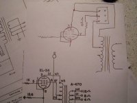
It allows for the 100 ohm resistor to be in series in normal UL operation. It also allows for triode operation. One side of a DPDT switch is shown.
Yep, that's the way I wired it. Go for it, Brian.
- Prasad
Would just changing the output tubes from UL to triode not change the plate resistance of the tube and therefore also being no longer optimal for the output transformator?
Amperex 6CA7/EL34
Triode connected, push-pull, 'class AB', values for two tubes:
Plate and screen voltage, 400
Idle plate and screen current, 130 ma, max signal, 142 ma.
Maximum signal output, 16.5 watts. THD, 3%
Plate-to-plate load, 5000 ohms.
Ultralinear connection: (screen taps located at 43% of plate
winding turns on OPT) . A 1 K resistor is required in series with each
screen grid to prevent its overload.
Plate and screen voltage, 500
Idle plate & screen current, 114 ma, max signal, 224 ma
Maximum signal output, 60 watts--(at)--THD of 2.5%
Plate-to-plate load, 7000 ohms.
Pentode connected: (using a common 750 ohm resistor
between the paralleled bypassed screens and the HV supply)
Plate and screen voltage, 500
Idle plate current, 60 ma, max signal, 204 ma.
Maximum signal output, 58 watts--(at)--THD of 6%
Plate-to-plate load, 5000 ohms.
Note in the case of the EL34, with more or less constant operating
conditions, the oprimum load Z appears, if anything, to go *down* as the
operating conditions are shifted from pure triode, to semi-triode to
pentode.
(although the only pure triode operating specs they published are for 400,
not 500 plate volts, the output Z for 500 volt pure triode operation would
be higher than that specified at 400 volts)
Since the screen current of a pentode such as the EL34 is not small
(compared to beam-power tubes such as the 6550 and 6L6GC) I would have
intuitively expected the load Z for triode operation to be significantly
lower than that of pentode operation due to the additional load of the
screens added to that of the plates. Instead, the opposite appears true.
This is all I have been able to find so far🙂
There are a number of people out there that have performed this modification and all claim it is superior in sonics and well worth the effort.
quadtech said:On some other forums, I have seen the following recommendations -
Shin Chin p/n R13-25B1-05 (Mouser 112-R13-25B1), rated 6A @ 250VAC.
Radio Shack # 275-636
I would humbly suggest you not "cheap out" on the switch. I use coin silver contact C&K DPDT (on-on) switches for this purpose, one per channel to minimize the extra wiring often needed with just one 4PDT switch for both channels. Not cheap, but I don't want failures.
While you are doing this mod, it may be a good idea to put the 100 ohm, 2W resistor right at the tube socket on pin 4 so that it is always connected in both UL and triode mode.
Or even use a bit larger Ohmic value, I use 274 Ohms .5 watt. The smaller wattage allows it to act as a "fuse" if a tube draws excessive screen current.
Maybe I've just been lucky for 30 years, but this article strikes me as a solution in search of a problem. Even with the Citation II supply that has a VERY low impedance I've never had any power tube arcing issues - although I don't use the cheapest junk tubes I can find in them. And maybe it's the larger resistance I use, I've never really analyzed why the failures described in the article don't take place in my stuff.
But do spend a few bucks more on some good switches, you'll be glad you did!
- Status
- Not open for further replies.
- Home
- Amplifiers
- Tubes / Valves
- Dynaco ST-70 Triode Conversion Techniques