The orignal circuit of st-70 has some drawback if you want to use it today. I did some mod to the original circuit to address those issues.
1. 16 Ohm speakers are not common nowadays. Changing nfb point to 8 Ohm tap makes more sense. As this change adds more gain after closing the feedback loop. The 390pf cap could be reduced as well.
2. 7199 tube is hard to find. The subtitude such as 6gh8 may have different bias point. Thus, I added DC negative feedback to lock in the bias point. The optimal voltage of the cathode of the triode portion of 7199 should be around 115v~125v. Here is a good writeout about this. https://www.angelfire.com/electronic/funwithtubes/pentode-triode.html
3. The shunt network (18K with 82pf) may not be necessary. I believe this portion is omitted in some of st-70 series II design. (Edited. I have played this for days with the oscilloscope. The amp is very stable without this network. There is a little overshot with sqarewave, but it is very stable. The original design is very aggressive. The amp has the gain-bandwidth product about 100KHz, which provides 20dB+ negative feedback at any frequency below 10KHz. It also reflects the engineer was very confident about its output transformer.)
Last edited:
The high plate impedance of the pentode drives the 18k and series capacitance (82mmf?, your added red wire obscured the number).
Why?
Because with the total circuit, and the exact original A470 output transformers, it needed a Dominant high frequency pole, to keep the amplifier stable with most speaker loads.
The dominant pole starts rolling off the high frequencies, at a lower frequency than the rest of the poles in the amplifier (poles like the output transformer, and other parts of the circuit [not much miller effect capacitance for a pentode, nor for a concertina phase splitter]).
Have fun modifying and getting it to run; then listen and enjoy!

The 7199 pentode plate impedance is 1 Meg Ohm.
That is in parallel with the plate load, RL, 300k.
The parallel 250k of plate and RL drives the 82pF and 18k.
You can calculate when 82pF = 250k Ohms.
that dominant pole is about 7kHz.
Is anybody surprised that the dominent pole high frequency rolloff is at 7 kHz.
Global negative feedback fixes the roll off, and so the frequency response is flat into multiple x 10 kHz.
But take it out, and you may have an oscillator.
The worst case high frequency roll off other than that dominant pole, is the output transformer, which is about -3dB at 60kHz.
If you use a different output transformer, that might help you do a first estimate of the frequency for the the dominant pole.
Have Fun!
The AC plate and cathode loads of the triode section of the 7199 must be equal for correct phase splitting. Yours aren't.
For most tubes, the voltage at the cathode of the concertina triode is more than the tubes rated cathode to filament voltage.
You need to elevate the filament voltage; 2 resistors dividing from B+, and a bypass cap will do.
Be sure to calculate the quiescent DC cathode voltage, and Add the maximum positive signal swing to it.
100V quiescent plus a 25V positive swing to get the output tube's grid near to the output tube's cathode, for example.
Did you take the time to check that? Probably not.🙂For most tubes, the voltage at the cathode of the concertina triode is more than the tubes rated cathode to filament voltage.
Attachments
I understand what you are talking about.The 7199 pentode plate impedance is 1 Meg Ohm.
That is in parallel with the plate load, RL, 300k.
The parallel 250k of plate and RL drives the 82pF and 18k.
You can calculate when 82pF = 250k Ohms.
that dominant pole is about 7kHz.
Is anybody surprised that the dominent pole high frequency rolloff is at 7 kHz.
Global negative feedback fixes the roll off, and so the frequency response is flat into multiple x 10 kHz.
But take it out, and you may have an oscillator.
The worst case high frequency roll off other than that dominant pole, is the output transformer, which is about -3dB at 60kHz.
If you use a different output transformer, that might help you do a first estimate of the frequency for the the dominant pole.
Have Fun!
The 82pf and 18K are omitted in the later ST-70 Series II design. https://www.thetubestore.com/lib/th...o/Dynaco-ST-70-II-Schematic-Owners-Manual.pdf
I did sqare wave test. Even without any load to the output transformer, it is stable.
For the dominent pole, the original 390pf cap plays a big role. That cap controls the unity gain bandwidth. Actually, you don't need to care about where dominent pole is. You should care about unity gain bandwidth.
They are equal if the input of the amp has 0 output impedance. They are close enough.The AC plate and cathode loads of the triode section of the 7199 must be equal for correct phase splitting. Yours aren't.
For most tubes, the voltage at the cathode of the concertina triode is more than the tubes rated cathode to filament voltage.
You need to elevate the filament voltage; 2 resistors dividing from B+, and a bypass cap will do.
Be sure to calculate the quiescent DC cathode voltage, and Add the maximum positive signal swing to it.
100V quiescent plus a 25V positive swing to get the output tube's grid near to the output tube's cathode, for example.
It is a good point. I did such mod on other tube amps but not on this st-70.
In dynaco st-70, the filament windings are float. The center tap of the filament winding is coupled to the groud only with a cap. Thus, the voltage between the cathode (7199) and the filament depends on the leakage, somewhere between the ground and the cathode voltage. In general, they are fine.
jxdking,
Thanks for your further discussions!
Did you use Original A470 output transformers, or a 'clone' A470, or a later model of A470?
Even the true A470 were not all constructed the same over the years.
Did you try loading the output with a capacitance, to simulate a long cable (and to simulate some loudspeakers and crossovers that are capacitive at high frequencies)?
You said: "Actually, you don't need to care about where dominent pole is. You should care about unity gain bandwidth."
And . . .
I say: "with a low pass filter that is -3dB at 7kHz, that will largely determine at what frequency the complete amplifier is at unity gain." . . . Right?
jdxing,
Dyna Stereo 70 amplifiers are well known for destruction of 7199 tubes.
I remember taking an Ohmmeter and measuring a destroyed 7199. The cold tube read 100k Ohms from the filament to the cathode.
A concertina that has 100k in parallel with Rk, and a ceramic cap from the secondary filament center tap to ground, makes the concertina not work properly, especially at mid and high frequencies.
"Sound Practices" Issue 10, "Save those 7199s!" by Matt Kamna, will tell you all about that.
Matt and I worked together at Tektronix, and we have been 'working audio' together ever since.
$0.30
adjusted for inflation
I have 4 stereo 70s and 2 SCA-35s. About half of the 7199s I tested when I got them tested low on the tester. Probably a third had the "rustling" noise, which I think is a sign of heater-to-cathode leakage. I never thought to put an ohmmeter on them though.
I've been following Dynaco tube circuit related info on the internet for 25 years now. Some historical info: Van Alstine claimed the Stereo 70 Series II was a direct copy of his Super 70 circuit, and the schematics I found indicate they are the same (with the 82pf 18k network) So it's possible the omitting of the network was not for performance reasons.
Various people have published their optimizations of the 7199 circuit, but it's hard to find complete info on these. I think the old TU-BE xeroxed publication from way back (70s?) suggested trimming the feedback compensation components in the circuit. I've also seen circuits with a trimmer and resistor in parallel with one of the pentode resistors to optimize the bias point.
The current Van Alstine Ultimate 70 also has a resistor divider on pin 3 of the 7199 to fix that voltage rather than rely on screen grid current. This is the circuit I'm using now, but as monoblocks with a maida regulator on the driver boards.
jxdking,
Thanks for your further discussions!
Did you use Original A470 output transformers, or a 'clone' A470, or a later model of A470?
Even the true A470 were not all constructed the same over the years.
Did you try loading the output with a capacitance, to simulate a long cable (and to simulate some loudspeakers and crossovers that are capacitive at high frequencies)?
You said: "Actually, you don't need to care about where dominent pole is. You should care about unity gain bandwidth."
And . . .
I say: "with a low pass filter that is -3dB at 7kHz, that will largely determine at what frequency the complete amplifier is at unity gain." . . . Right?
Hi @6A3sUMMER
The compensation approach of st-70 is very clever.
It is done through the 1K resistor and the 390pf cap. At low frequency, the nfb is through the 1K resistor, while at high frequency, the nfb is through the 390pf cap. The 390pf is connected from the grid 2 of the output tube, before the transformer. Thus, the high frequency stability of the amp does not depend on the transformer or the load. As said, at high frequency, the transformer is not inside nfb loop.
The next question is at what frequency that we can say "it is high freqeuncy". If the transition point is too high and the transformer is still inside the loop, the amp may not be stable. At the transition point, the current over the 1K resistor should equal to the current of the 390pf cap. If the frequency is higher than that, the cap will conduct more, vice versa. Also by given the voltage ratio between the resistor and cap (the votage ratio is determined by the transformer), you should be able to layout the formula to get the transition frequency. Actually, you don't need to caculate the frequency, as long as you keep the same ratio of R and 1/C, the transition point should stay the same. As long as you keep the ratio as the original design, the amp should be stable. PS: if you change the feedback point from 16 Ohm tap to 8 Ohm tap, this ratio need to be adjusted accordingly.
The "unity gain bandwidth" is the same thing as "transition frequency" I talked above.
Lets say the trainsition point is 80KHz, if the amp has 20dB nfb (about 10 times), the dominent pole will be at 8KHz.
Regarding 82pf and 18K network, I believe it is used to supress the high frequency ringing. At high frequency, there are only 3 active devices (tubes) inside the nfb, pentode portion, triod portion, and the output tube. There would be 3 poles. Because one of them, the pole at the cathode of the pentode is very high so that you can ignore, it is kinda stable enough. However, it may still exhibit ringings without the 82pf and 18K.
I don't like the shunt compensation. It is a brutal way to limit the gain. The alternative way is to use local nfb to reduce the gain, as the 47pf that I added to the circuit (in the OP). The local nfb lowers the output impedance of the output tube. It will be more linear than the shunt implimentation.
Last edited:
I have 4 stereo 70s and 2 SCA-35s. About half of the 7199s I tested when I got them tested low on the tester. Probably a third had the "rustling" noise, which I think is a sign of heater-to-cathode leakage. I never thought to put an ohmmeter on them though.
Thank you guys.Dyna Stereo 70 amplifiers are well known for destruction of 7199 tubes.
I remember taking an Ohmmeter and measuring a destroyed 7199. The cold tube read 100k Ohms from the filament to the cathode.
A concertina that has 100k in parallel with Rk, and a ceramic cap from the secondary filament center tap to ground, makes the concertina not work properly, especially at mid and high frequencies.
"Sound Practices" Issue 10, "Save those 7199s!" by Matt Kamna, will tell you all about that.
Matt and I worked together at Tektronix, and we have been 'working audio' together ever since.
I threw away 2 7199 tubes in the past that as you discribed with "rustling" noise. I thought just because of the old age.
I will investigate more regarding filament voltage issue. If they cannot float to a proper voltage, then they have to be strapped.
Last edited:
I use a fixed voltage divider for the filaments in my Dynacos, I adopted it to reduce hum. I always found I could get a little low level 60hz hum with the original floating filament with capacitor grounding that Dynaco did. I've had 6GH8's get the rustling noise even with the fixed filament voltage.
jhstewart9,
Yes, the data sheet corrects me, 200V peak cathode to filament. The signal excursion was Not the problem.
But . . . my problem was caused by the max rated Average cathode voltage of 100V; it measured 120V.
Of course, my mains power that sometimes is as high as 123VAC, that will cause a 117VAC Dyna Stereo 70 to have higher B+ than normal.
with a primary to secondary step up of about 3, and raising the mains by 6V, the B+ increases by about 18V.
That might have accounted for the concertina cathode being at 120V average (120VDC quiescent).
Or, if the pentode section went weak, its plate voltage would increase, and drive the concertina grid higher than normal.
. . . This all happened back in about 1995, 20 years ago. Since then . . . Lots of water under the bridge, and some lesions on the brain too.
Most 7199s that are replaced by another pentode triode pair such as 6AN8, either require a new PCB, or a lot of hacking of the original PCB traces to the tube socket.
Last edited:
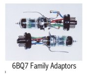
I built my own adapters for 12A_7 to other tubes, such as 6J6 and others.
Of course those adapters work for some circuits without needing resistor changes;
and do Not work at all for some other circuits, even with resistor and capacitor changes.
Of course those adapters work for some circuits without needing resistor changes;
and do Not work at all for some other circuits, even with resistor and capacitor changes.
My home grown adapters stuff a 6BQ7 into a socket designed for 6SL7 or 6SN7 with -150V resistive tail.TubeDepot sells a 6u8 adapter for those pricey replacement 7199's
The 6SN7 adapter has 1K resistor n each cathode to reduce the gain. So 2-stage Diff Amp.👍
Attachments
- Home
- Amplifiers
- Tubes / Valves
- Dynaco ST-70 Mod