I am rebuilding a PAT-4 , I would like to change out the I/O board and eliminate the tape head , special , high level & ceramic phono inputs. I would also like to add one high level input for a total of three high level inputs. My question is this does any one know what wires to disconnect from PC boards ,if I just clip leads at the RCA jacks it creates a bad hum problem.
My second question is if I remove two of the phono inputs can the PEC removed and if so what value resistor would I need on the low level inputs for a Shure M97xE cartridge.
Thanks in advance for any help
My second question is if I remove two of the phono inputs can the PEC removed and if so what value resistor would I need on the low level inputs for a Shure M97xE cartridge.
Thanks in advance for any help
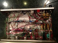
Attachments
google has two links to the PAT4 construction manual :
Dynaco PAT-4 | Owners Manual, Service Manual, Schematics, Free Download | HiFi Engine
and www.updatemydynaco.com/pat4.html
This will tell you where the wires go.
The second link has kits to change the PWB's of the amp.
I have my doubts about changing the number of high level versus low level inputs. The PAT4 uses a rotary switch with a certain number of poles (4 probably) and a certain number of throws. Two of those poles are dedicated to low level inputs. You couldn't convert two of the throws of that element to high level without changing wafers to provide an additional pole. They don't make centralab rotary switches anymore, IMHO. So going to 4 high level inputs and 1 low level requires replacing the switch with a relay or solid state switching arrangement.
I abandoned the whole selector/switch/preamp thing and went to a mixer for everyday use. All inputs are hot all the time and you don't have to move the volume knob everytime you switch from mag phono to CD. A mixer PWB allows you to change the gain on inputs by just changing the feedback resistor on the op amp. I converted a 2 turntable one CD player one mono dynamic microphone input mixer to a 2 turntable one CD player one stereo FM radio input mixer by fiddling with the wiring and the gain. You could also take a normal band mixer, and fiddle with two inputs to make it RIAA phone compatible.
I am also using a M97 era IV cartridge, going on 34 years old now.
Good luck.
Last edited:
You can also find nice pdf's of the PAT-4 manual here:
The PAT-4 Pages
the first two links, right at the top of the page, are the first and second halves of the pat-4 assembly manual, and include the large wiring diagram.
The PAT-4 Pages
the first two links, right at the top of the page, are the first and second halves of the pat-4 assembly manual, and include the large wiring diagram.
- Status
- Not open for further replies.