Hi there please take a look see what you think.
Edit: un-mod
The original topology wasn't all that bad, I think when Hi-Fi Review did
The measurements, they found the RIAA to be around .5dB off from the 1kHz reference.
The original topology wasn't all that bad, I think when Hi-Fi Review did
The measurements, they found the RIAA to be around .5dB off from the 1kHz reference.
But in my view there is a flaw. The actual level drop of the bottom at the far side is more than 0.5db, that by time when it reached line amp input. What is the basis of modification then? Why people mod it and based on what ground? Why did the level drop off at bottom end at line amp input? The can be explained simply because the output impedance of the riaa at bottom end is too high, and output impedance I measure @ point 5 is about 90K at higher frequency, but double to 180k at bottom end. I could be wrong, is this correct?
Last edited:
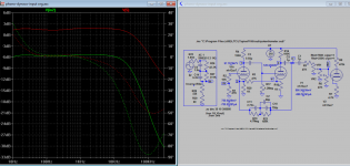
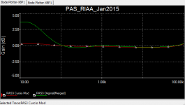
Please take a look see you agree with me. I change the output and input cap from 0.1u to 1u. This flatten the bottom end for both side nicely (output impedance is lowered as predicted) 🙂
Shows up nicely, correcting the positive feedback gives about the same effect as well,with the feedback correction, I'm able to bring the size of the output cap up to about .47uf and still have a very flat response on the bottom end. When I'm back at comp. I can post the pic of the Spice run.
Displaying simulated curves is not reality, it's a predicted behavior that could be far from reality, especially as outer parameters are left out ( loading on tape-out is
one such parameter, connecting a "typical load" here might alter the result)
It's the actual performance ( how a PAS-3 sounds and measures) that is important.
one such parameter, connecting a "typical load" here might alter the result)
It's the actual performance ( how a PAS-3 sounds and measures) that is important.
Thanks for all your answers!
I really appreciate your time spent on this.
I´m a little bit confused right now what to do and think. Regarding to the 11 page document regarding the RIAA-stage, and also "the great upgrade" for the board, I think the best thing to do right now is at first bring back the original data and performance for both the RIAA and line-board.
Together with that also fix the power supply, in the same way you mention Peter. All new caps in the power supply and silicon diodes for the heater, but keep the 6X4-tube.
Together with rewiring the input to the selector switch, I think that will be a good start to listen and evaluate the line and RIAA stage.
From that point, when I know the original performance, then it´s time to discuss mods again.
Thanks for all the good input, and let the discussion go on, it´s interesting to see and read.
Best regards
Rampitsch
Denny-
Thanks for the the info. As near as I can remember, I followed Curico’s suggested values which means that the feedback resistor is left at 47Kohms. The 1.2 Mohm load is retained for the first stage while the load on the second stage is reduced to 3.095 Mohm (2Mohm+95Kohm). As I recall I have the B+ set at 340VDC against Dynaco’s original 210VDC.
I haven’t specifically noticed “weak bass” but I’ll certainly look into your suggestions.
If someone wants to use the Koren line stage, and is willing to forgo tone controls, the job isn’t all that bad. Below is a photo of the inside of my PAS before I “buttoned it up” nearly 5 years ago. The original phono board is just visible at the bottom of the picture, as is the new power supply in the location of the original heater supply. Since newer caps are far more compact that those of 50 years ago, I moved the heater supply to the location of the original recifier tube. This power supply isn’t a necessity to power the Koren line stage; his article outlines some easy changes that are satisfactory. The new Koren board may be (that’s might be) still available. If there’s interest, I’ll check with the supplier.
However, adding Koren’s optional tone controls greatly increases the complexity of the job. One of my home-made boards is visible mounted vertically at the upper right. There’s a bunch of other stuff barely visible behind it, including the pots.
If I build another, I may skip the tone controls!
Attachments

Displaying simulated curves is not reality.
Get's you pretty darned close...
FWIW, you can tune the capacitors in an RIAA section with a pair of variable caps.
This was my first modification of the PAS -- with Curcio's RIAA --
the power supply modification is based upon "Modifying the Marantz 7C or St. Pooge and the DRIAAGON" (The Audio Amateur 1/81 pp 20..37)
Very quiet, but i never ran it through the battery of tests as i did for the Linear Audio article. (didn't have the equipment or know-how).
An externally hosted image should be here but it was not working when we last tested it.
the power supply modification is based upon "Modifying the Marantz 7C or St. Pooge and the DRIAAGON" (The Audio Amateur 1/81 pp 20..37)
An externally hosted image should be here but it was not working when we last tested it.
Very quiet, but i never ran it through the battery of tests as i did for the Linear Audio article. (didn't have the equipment or know-how).
my inputs
2 cents and totally from memory so do check my input.
replace the incandescent bulb with an LED (with resistor in series)
and adjust the resistor depending where you tap the voltage. I recall
that the tubes for each board have their heaters wired in parallel so the
voltage will be 25v or so. I used a blue LED. this lowers the load on
the trafo.
the RIAA section is pretty standard for that era so the RIAA feedback
network is similar among all of them. I think/recall that the curcio
mod is similar if not identical to the Conrad Johnson version.
I would be very, very careful regarding messing with that selector switch
since there are two ground circuits (phono, Line) and you could get HUM
if you mess with it (there's also the third ground if you move to a
three prong plug and ...)
On the selector, you could wire the unusable (tape head, and others)
to the phono circuit by adding a switch (replacing the useless blend)
and be able to select from multiple turntables.
on the back panel there are set of 5 then 4 RCA jacks for input and
output: you could reduce the number on each and drill a new
PCB board and mount better quality RCA jacks. There are 10R(?)
resistors on one of the panels that needs to be also present on the
new boards.
for power input, use an IEC (your decision on what to do with the
power ground), add an external fuse mount. and don't use those
old female power plugs - their ratings are low and they are now about 50 years old.
lastly, most improvements (Koren et al) add a Cathode Follower but
the existing power trafo doesn't have enough B+ current nor heater current
capacity for tube CFs. You could very easily add OPamp buffers and
a power supply instead (I believe that Jensen did offer this at one time).
good luck, I think updating PAS2/3s are a great project.
Bob
The PA211 replacement transformer from Triode Electronics delivers slightly more heater and B+ current then the Dyna originals. Not a lot, but a little. It will power 5 (no more) 12AX7 heaters to about 12+ volts, if the indicator lamp is replaced with an LED.
The HV is sufficient to develop 340-350 VDC to both boards (again 5 tubes) with no regulator.
My next PAS will either be built with an external power supply, or in an old SCA-35 chassis that I’ve had lying around for years.
The HV is sufficient to develop 340-350 VDC to both boards (again 5 tubes) with no regulator.
My next PAS will either be built with an external power supply, or in an old SCA-35 chassis that I’ve had lying around for years.
replacing the 12x4 with 2 1n4007 will give the margins to run a 5 heater, but B+ is still marginal.
I test the 1uf caps no joy!
I tried the above replacing the .1uf with 1.0uf caps and at half volume you get clipping on the high freqs. So I am going to try .1uf and .47uf and see how that sounds, as per the Bob Latino phono mod.
Please take a look see you agree with me. I change the output and input cap from 0.1u to 1u. This flatten the bottom end for both side nicely (output impedance is lowered as predicted) 🙂
I tried the above replacing the .1uf with 1.0uf caps and at half volume you get clipping on the high freqs. So I am going to try .1uf and .47uf and see how that sounds, as per the Bob Latino phono mod.
Hi
maybe I get mobbed for blasphemy here but I was thinking to put a powerfet on the output to act as a cathode follower instead of an extra valve to better drive the RIAA-cirquit. I don´t really like the feed forward loop in the PAS as it tends to enhance subsonic disturbances. It´ll take at best three extra components to do this and some recalculations on the voltage gain for each of the valve sections. Any interesting suggestions out there?
maybe I get mobbed for blasphemy here but I was thinking to put a powerfet on the output to act as a cathode follower instead of an extra valve to better drive the RIAA-cirquit. I don´t really like the feed forward loop in the PAS as it tends to enhance subsonic disturbances. It´ll take at best three extra components to do this and some recalculations on the voltage gain for each of the valve sections. Any interesting suggestions out there?
This is a board that fits inside the PAS and is powered via the filament power.Hi
maybe I get mobbed for blasphemy here but I was thinking to put a powerfet on the output to act as a cathode follower instead of an extra valve to better drive the RIAA-cirquit. I don´t really like the feed forward loop in the PAS as it tends to enhance subsonic disturbances. It´ll take at best three extra components to do this and some recalculations on the voltage gain for each of the valve sections. Any interesting suggestions out there?
Dynaco PAS Preamp Impedance Matching Module New! | eBay
I have tested one ( and reengineered the schematics) and it works fine without adding dist or hum.
Hi and thanks petertub but what I´m addressing is the problem in the riaa-section that has the sub-frequency hump that makes the woofers flab dangerously, specially if they are of bass-reflex type. Driving poweramps with lower input imedances is nearly of no concern if the tone-section is bypassed, distorsion will get up but frequency response will be perfect, due to its feedback, way down to 10kohms and with an output capacitor big enough. BUT In the riaa-section the openloop gain is barly high enough get away with it, hence the sub-hump. My suggestion is about another solution than mr. Cursio and others have precented and more towards a ARC-fashion.
Hi, (again) well I´ve now tried this on the RIAA section and can only say it works and measures perfectly with some HF compensation tricks though, no big deal. The sound is more detailed and powerful in the whole spectrum without getting solid-state hard or annoying, just plain better I think. I used a IRF 710 Fet and a 1,5uF SCR/Solen output capacitor. With a bypassed tone section in the line stage I even think the sound from this PAS 3 now is as good (better?) as a standard (not tampered with) ARC SP3a-1 I have at my desposal.
Details please. It's always nice with ideas and inputs.
Myself made a couple of cathode followers, one for the tape/computer out and one for the line out. That and keeping 250k volume pot keeps my PAS happy. It's documented elsewhere.
Myself made a couple of cathode followers, one for the tape/computer out and one for the line out. That and keeping 250k volume pot keeps my PAS happy. It's documented elsewhere.
No, no details from me, too heavy (se below), just saying it works and for those who are willing to try. It will pay off also with more headroom and almost symetrical clipping. But here´s some input I got somewhere else. I found out it was not only me who thought of the same thing. ;-)
Project 167
Project 167
- Home
- Amplifiers
- Tubes / Valves
- Dynaco PAS 3X - help with an old modification