Hi all,
The circuit I have attached is a mod for my MKIII kit. The circuit works. It's all biased up and sound incredible on an old pair of old of Optimus Radio Shack bookshelf speakers. My B&W's will really bring them to life 🙂
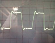
An area of amp design I need to work on is square wave performance. I have been for a while messing around with trying to combat that ringing. My job requires me to work offsite for the next week and I do not have my square wave generator on hand. I built one with a 555 timer, which is why the duty cycle is around 2/3 and there is some hysteresis. I do not think that matters though, square waves are square waves.
Note the low pass filter coming off the 12AY7 SRPP. Trying different values helps somewhat for the R and C.
The really tricky part is the cap filter in the feedback network. Adding a large cap (> 150pF or so) there knocks down the ringing but causes all kinds of fuzz on top of the square wave. Same with the sine wave as well.
Questions:
What exactly should I be aiming for? Someone else said I need to attain a rounded corner. Doing that seems to be difficult. Another balked at the idea of even putting in those filters. Without them the amp probably will go unstable with the right reactive load.
With the filters I have, am I barking up the wrong tree? Should I try other filtering schemes?
The circuit I have attached is a mod for my MKIII kit. The circuit works. It's all biased up and sound incredible on an old pair of old of Optimus Radio Shack bookshelf speakers. My B&W's will really bring them to life 🙂
An area of amp design I need to work on is square wave performance. I have been for a while messing around with trying to combat that ringing. My job requires me to work offsite for the next week and I do not have my square wave generator on hand. I built one with a 555 timer, which is why the duty cycle is around 2/3 and there is some hysteresis. I do not think that matters though, square waves are square waves.
Note the low pass filter coming off the 12AY7 SRPP. Trying different values helps somewhat for the R and C.
The really tricky part is the cap filter in the feedback network. Adding a large cap (> 150pF or so) there knocks down the ringing but causes all kinds of fuzz on top of the square wave. Same with the sine wave as well.
Questions:
What exactly should I be aiming for? Someone else said I need to attain a rounded corner. Doing that seems to be difficult. Another balked at the idea of even putting in those filters. Without them the amp probably will go unstable with the right reactive load.
With the filters I have, am I barking up the wrong tree? Should I try other filtering schemes?
Attachments

Do you mean the lead-lag compensation network R10/C12? This might not work too well as the output of an SRPP is a fairly low impedance point, unlike a straightforward triode anode. At the very least you will need a low impedance network which will partially reduce the benefit (if any) of using an SRPP.kingneb said:Note the low pass filter coming off the 12AY7 SRPP. Trying different values helps somewhat for the R and C.
It might be useful to estimate the frequency of the ringing you are seeing. Also, what looks to be ringing might not actually be caused by an HF resonance - a sharp HF cut can do something which looks quite similar in the time domain.
Provided the frequency is well removed from any audio signal you will be sending to the amp then it should do little harm. Complete removal of ringing may only be possible with a reduction of treble too - it all depends on details of the HF poles in your loop.
You may be able to make some progress in simulation, provided you have a good model for the OPT.
Questions:
What exactly should I be aiming for? Someone else said I need to attain a rounded corner.
The amount of GNFB is in important role. With reasonable 10...12 dB GNFB the ringing is not usually a problem and good transient response is easier to achieve.
How much is GNFB now ?
I would never let the rounding take place i.e. to let the frequency response fall in vain.
An other thing: try to measure with 10 kHz square wave. It gives better information.
This is an example of good 10 kHz square wave response: (from my 100 W circlotron)
An externally hosted image should be here but it was not working when we last tested it.
I notice you have some ringing still, no big deal, that's great. Did you just knock it down with a FB cap or is that just the natural response of your circlotron?
First condition to low ringing and good transient response is good output transformer with low leakage inductance.
As I said earlier, the amount of GNFB is also very important factor. It is not practical to use more than acceptable THD-level and output impedance require.
Often some 10...14 dB is enough assuming the whole circuit is well optimized.
To above photo:
If the feedback loop capacitor were taken away the ringing would increase percepibly.
On the other hand, if the capacitor were too big, the rounding of the square would take place, also frequency response would fall and transient response would be worse.
The photo represents about the optimum and this situation is easy to achieve with an oscilloscope.
First order of business is to lower the FB, I had around 15-20dB or so in there with the
12AY7. I am replacing it with a 12BH7 to lower the FB requirement for 1.5 volt sensitivity.
C11 alone just will not cut it with 18Db of feedback.
12AY7. I am replacing it with a 12BH7 to lower the FB requirement for 1.5 volt sensitivity.
C11 alone just will not cut it with 18Db of feedback.
The effect to ringing, instability etc. is significant when GNFB is adjusted from 20 dB to 15 dB. If you replace 12AY7 with 12BH7, then you should adjust the bias for optimum THD.
You could also remove R10 and C12, because of the reasons told above.
You could also remove R10 and C12, because of the reasons told above.
I elected to keep the 12AY7 and ditched the SRPP since the same circuit will go into a stereo 70. That way I can use 3 tubes instead of 4.
What do you think about this square wave? The whole reason for the 18dB of feedback is to maintain the original Dynaco spec and knock the distortion down into the 0.3% locale. Do you think the distortion number exercise is silly? if so I will consider lowering the feedback. The 12BH7 trick I may revisit tomorrow.
Good idea to keep 12AY7. If the sensitivity need adjustment, a simple attenuator at the input does this job.
The amount of GNFB should never be selected for sensitivity adjustment purpose.
Your square wave is good, especially as the circuit is typical push-pull and the amoun of GNFB is that big.

0.3 % THD level should be easy to achieve with less GNFB if all parts of the amplifier are optimized, especially the output stage bias, bias-balance and AC-balance.
I am sorry, I kept saying 18dB. It is 15. Will try to take it down to 12 or so and optimize phase splitter and bias and see what happens.
I am used to solid state and using feedback to set gain. Just a conflict with the times I guess. Happen to anyone else?
I am used to solid state and using feedback to set gain. Just a conflict with the times I guess. Happen to anyone else?
I try to describe the effect of the amount of GNFB to the transient response by few plots of LTSpice simulations. The used signal is 10 kHz square wave.
The plots are in the following order:
1. NO GNFB
2. 7 dB GNFB
3. 10 dB...
4. 16 dB...
5. 10 dB GNFB with optimum Cfb
Can you observe similar behaviour with your amp ?
The plots are in the following order:
1. NO GNFB
2. 7 dB GNFB
3. 10 dB...
4. 16 dB...
5. 10 dB GNFB with optimum Cfb
An externally hosted image should be here but it was not working when we last tested it.
An externally hosted image should be here but it was not working when we last tested it.
An externally hosted image should be here but it was not working when we last tested it.
An externally hosted image should be here but it was not working when we last tested it.
An externally hosted image should be here but it was not working when we last tested it.
Can you observe similar behaviour with your amp ?
Big time. I stayed up until 4:00 AM doing just that. Not in spice but with a scope and pattern generator. I woke up at 9:00AM and am sticking in a FB pot to find a sweet spot.
Is the ringing caused by energy being released from the transformer, being that it is an inductor? Similar effects I need to combat in switching power supply design.
Is the ringing caused by energy being released from the transformer, being that it is an inductor? Similar effects I need to combat in switching power supply design.
Last edited:
Leakage inductance of the primary of the output transformer is the main cause.
If it is low, then ringing is low and frequency response is wide, even without NFB.
Leakage inductance can be easily measured.
Just connect the inductance meter between center tap and one end of the primary and short the secondary. The inductance that remains is leakage inductance of the primary half.
The value depends also on the inductance of the primary, but can be within 1mH ...40 mH. The smaller the better.
Last edited:
Unfortunately, it is kind of a crap shoot with leakage inductance as component datasheets tend not to list it. How are torroids in this fashion?
Are you seeing transformer ringing, but damped by the NFB - or the verge of loop instability due to the transformer HF resonance and other phase shifts? Probably the latter, in which case understanding loop stability (e.g. Bode plots) may be part of the solution. You could make a start by estimating where your HF poles are, and making sure they are well separated in frequency. Open-loop measurements may help.
Unfortunately, it is kind of a crap shoot with leakage inductance as component datasheets tend not to list it. How are torroids in this fashion?
The plot you earlier showed is quite good.
Where do you see the problem ?
I have no experience with toroid OPT's.
Tomorrow I will install the optimal cap values. I'm about to crash. Not a good idea to work on high voltage stuff when tired. Learned that lesson with the magic smoke :; At work, the boss is impressed because I can never quit. It must work and it must work tonight!
As far as torroids go, the only thing that turns me off is their high cost. About $1000 for two custom power trannies. My pet name for them is doughnuts because they look good enough to eat.
As far as torroids go, the only thing that turns me off is their high cost. About $1000 for two custom power trannies. My pet name for them is doughnuts because they look good enough to eat.
Here is the information for the existing system.
I have ~15dB of global feedback. Attached is the square wave response. That is the best I can get it. It does not look like it is ringing, but there is a spike in the upper left portion. The amp is not oscillating, yet. What do you think?
I have ~15dB of global feedback. Attached is the square wave response. That is the best I can get it. It does not look like it is ringing, but there is a spike in the upper left portion. The amp is not oscillating, yet. What do you think?
Attachments
Quite good and very typical with standard OPT's including Hammond and Edcor.
The slight ringing, which still is visible, can be fully erased only by spoiling the frequency response.
Can you measure what the high end frequency response is ? To me it seems to be some 50 kHz (-1 dB).
I would not do anything more GNFB adjustments.
The slight ringing, which still is visible, can be fully erased only by spoiling the frequency response.
Can you measure what the high end frequency response is ? To me it seems to be some 50 kHz (-1 dB).
I would not do anything more GNFB adjustments.
I have not checked the high roll off but down at 20Hz the Pk-Pk voltage is about ~2 or so volts less than the 1KhZ reading.
I tried adding in 100k grid leak resistors instead of the 27k but there was no effect. I assume that transformer starts rolling off somewhere in the 30s, or possibly the 40s. I do not have my arbitrary waveform generator on hand so I had to use Audacity to generate it. Is it also possible my laptop's audio board or audacity rolls off?
The transformer is supposedly a reproduction of the MKIII's Z-216. Not sure what the response was supposed to be for that unit. I bought it originally as part of a kit from Welcome to DYNAKITPARTS.com The guy who operates that outfit would not tell me who manufactured it, probably an NDA type situation.
Dynaco Mk 3 mod to Jadis JA80
I modifed my MK3 to Jadis JA 80, the waveform is very good. You may try and I think you will get good result. Good luck
I modifed my MK3 to Jadis JA 80, the waveform is very good. You may try and I think you will get good result. Good luck
- Status
- Not open for further replies.
- Home
- Amplifiers
- Tubes / Valves
- Dynaco MKIII mod