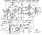
Hi, just got a second hand Dynaco's mk3. Bought it as a modded ones.
Upon inspection, I found that the ultralinear taps unused and instead to have a separated transformer feeding a 240Vdc to the pins 4 of the 6550 output tubes.
I have to say that this amp do have a solid state rectifiers and extra 1000uF at 800Vdc caps of power supply filtration.
B+ is at 500Volts.
It use the standard 6AN8 input/driver boards.
I know in certain Heathkit and Fisher amps the screen supplies are derivative from B+ with RC filters, but why not use ultralinear taps on original output transformers??
I know that the ultralinear taps are part of the design of Dynaco to minimize THD. Globalized with NFB.
Just a curiosity.
I know in big FM transmitter plate B+ supply do have a separated screen supply, make sense in non output transformer design as FM is RF couple to the antennas.
🙂
People like to modify.
When they modify, things are different.
Generalizations:
6550:
Some like Pentode Mode. Highest open loop gain, highest plate resistance, rp.
Highest power, highest open loop distortion.
Some like Ultra Linear. Medium open loop gain, medium plate resistance, rp.
High to medium power, high to medium open loop distortion.
Some like Triode Mode. Lowest open loop gain, lowest plate resistance, rp.
Lowest power, lowest open loop distortion.
Open loop means with no negative feedback. Adding negative feedback changes things.
But inside the loop, the above characteristics of the 3 modes remains.
All 3 modes have tradeoffs and advantages.
Care to try Triode Mode?
Except for the major power supply changes, did the modifier make any other changes including the global feedback parts or circuit?
Only the modifier knows why he/she did it.
Yes, I know , and I be tempted to put it back to original design, ultralinear, 5AR4 rectifier, Pentode scheme.
Mostly not looking at power available, but mostly fidelity with the new input/driver board like Poseidon pcb's using 12AX7 and 12BH7A's
It makes maybe sense in DC manner to have a lower screen voltage, but as I always understand it, ultralinear from output transformers taps are there also for AC characteristics. A sort of local partial feedback in the 6550 output tubes.
Thanks.
In my opinion, for conservative operation and long life, Beam Power tubes and Pentode tubes should have 3 maximum screen voltage ratings:
1. Beam Power / Pentode Wired Mode
2. Triode Wired Mode
3. Ultra Linear Mode The maximum voltage would depend on the UL tap percent (%).
The higher the percent, the more the screen voltage can be like Triode mode (I have used 50% and 80%).
An example of 1. and 2. above is the 807.
Maximum screen voltage in Beam Power mode was/is 300V.
Maximum screen voltage in Triode mode is 400V
I estimate the unrated maximum screen voltage in Ultra Linear mode to be about 350V.
Just think about the above 3 modes, how the mode affects the relation of the screen and plate voltages. Then look at all the curves, including the screen current curves at various fixed screen voltages versus the plate voltages, and decide for yourself.
Guitar Amplifiers are the exception; but if you have to abuse an output tube in a Hi Fi amplifier, you should be using a more powerful output tube.
And just because a Hi Fi amplifier is made by a well recognized company, does not mean the designer did not exceed one or more of the output tube maximum specifications. I have seen some abuse in some of those amplifiers.
A Tungsol data sheet shows 6550 maximum screen voltage as:
Pentode Connection (Beam Power) 440V
Triode and Ultra Linear Connection 500V
Just my opinion.
Last edited:
stereohifi,
You are correct,
The UL taps provide local negative feedback to the output tube(s).
I had a push pull amplifier with 40% taps.
I have designed and built single ended amplifiers with 50% and 80% UL taps.
You are correct,
The UL taps provide local negative feedback to the output tube(s).
I had a push pull amplifier with 40% taps.
I have designed and built single ended amplifiers with 50% and 80% UL taps.
Sounds like a paoli modification.Hi, just got a second hand Dynaco's mk3. Bought it as a modded ones.
Upon inspection, I found that the ultralinear taps unused and instead to have a separated transformer feeding a 240Vdc to the pins 4 of the 6550 output tubes.
I have to say that this amp do have a solid state rectifiers and extra 1000uF at 800Vdc caps of power supply filtration.
B+ is at 500Volts.
It use the standard 6AN8 input/driver boards.
I know in certain Heathkit and Fisher amps the screen supplies are derivative from B+ with RC filters, but why not use ultralinear taps on original output transformers??
I know that the ultralinear taps are part of the design of Dynaco to minimize THD. Globalized with NFB.
Just a curiosity.
I know in big FM transmitter plate B+ supply do have a separated screen supply, make sense in non output transformer design as FM is RF couple to the antennas.
🙂
However, no fear. You have most parts to rebuild it to a genuine MkIII
Some of the early non-American 6550's (we did not always have lots of reliable alternatives available like we do today) did not handle elevated G2 voltages very well,and it was often necessary to change from Ultra-Linear operation to straight pentode in order to reduce the G2 voltage in an effort to alleviate frequent power tube failures.
While this was an effective work around,it did change the character of the amp,especially at high operating levels or overload conditions.
I would be more than a little concerned about running SS rectification with 1000µf of capacitance on an original Dynaco power transformer,at least not without a substantial inrush current limiter.I still believe it to be too much for the transformer under normal operating conditions.
Ok, you have a choice then, keep it as one of the few remaining paoli's ( they were reported to be very good !, a friend even made boards to populate mostYes, that's it a paoli 60M with the side power supply.....
of the changes but i never rebuilt mine)
Dynaco Mk 3 Paoli design??
No, I won't keep my MK 3 to a Paoli design, they are back to originals now, tube rectifier, all new parts, etc.
But just got a P782 power transformer issue, primary just shorted, damn
I highly suspect because of this Paoli mod with SS rectifier and 1000uF of capacitance, it made metal wiring fatigue and blew short the primary.
One of them, and now maybe the second one will blew too????
Sorry but the Paoli mod is no good for longevity.
I know some original MK 3 to have more than +40years without issues like that.
Be sure to check the value of the 6550 g1 resistors.
For fixed bias, the g1 return is supposed to be 50k Ohms or less.
I once had a red-plated 6550. It was caused by fixed bias, and the unusually large resistance of the g1 return resistor.
Changing the resistor to 50k fixed the problem.
For fixed bias, the g1 return is supposed to be 50k Ohms or less.
I once had a red-plated 6550. It was caused by fixed bias, and the unusually large resistance of the g1 return resistor.
Changing the resistor to 50k fixed the problem.
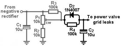
No problems with bias as I have implemented in many different tube amps with this bias charge mod.
Idea came from: The Valve Wizard
I have a Fisher and Heathkit 6L6GC based amp with this bias scheme, even a Rogue Magnum 120 that was cathode bias id modded this way...
Idea came from: The Valve Wizard
I have a Fisher and Heathkit 6L6GC based amp with this bias scheme, even a Rogue Magnum 120 that was cathode bias id modded this way...
Attachments
stereohifi,
That is a good bias network . . . except that it is about 100k to ground.
The 6550 g1 sees > 100k from the bias network, and then you have to add to that the g1 grid leak resistor.
If the g1 grid leak resistor is 100k, then g1 sees 100k + 100k (200k to ground).
That is 4X more than g1 requires . . . 50k to ground.
Your tube mileage may vary.
6L6 max g1 resistor is 100k, 6550 max g1 resistor is 50k.
Those bias network values do not meet the requirements, because nobody uses 1 Ohm grid leak resistors (no driver wants to drive that).
If your driver stage can only drive higher resistance g1 grid leak resistors, then use cathode self bias on the output tubes.
That raises the max g1 grid leak resistance up to lots more than fixed bias max g1 resistor.
Last edited:
> it is more than 100k to ground.
When diode conducts it only adds a few K ohm. And on first glance, any "dangerous" shift of grid voltage will forward-bias the diode. So Merlin suggests.
There's also no clear reason the 100k can't be 10k.
That added network may be more relevant in Guitar Amplifier. It catches a sudden turn-off/on sequence. That does happen on stage as cords get tripped; maybe not so much in domestic hi-fi.
Dynaco MK III
If we look at a Dynaco Mk3 grid of 6550-KT88 is DC seeing 100Kohms + 1Kohms + 10Kohms pot. and 18Kohms to ground, to the bias supply.
Potentiometer might be in half position, so let's say 5KOhms
Still grid of the 6550 seeing 124Kohms.
With the bias circuit of tube wizard, yes the added 100Kohms if applied in this circuit, which I did, one for each tube in fact, is yes a bit to much.
Attachments
stereohifi,
KT88:
Rg1-k (fixed bias)
Wa+g2≤35W 220kΩ
Wa+g2>35 W 100 kΩ
6550
Rg1-k (fixed bias)
50 kΩ
I think you can see a (the?) major difference between a KT88 and a 6550.
Red line Ferrari; Red line Volkswagen, respectively.
KT88:
Rg1-k (fixed bias)
Wa+g2≤35W 220kΩ
Wa+g2>35 W 100 kΩ
6550
Rg1-k (fixed bias)
50 kΩ
I think you can see a (the?) major difference between a KT88 and a 6550.
Red line Ferrari; Red line Volkswagen, respectively.
Another P782 blows!?
Yes upon testing and bring power with a variac, saw the main 4A s.b. flashed, primary is short.
second one now.
Mind you both of my amps work with another close spec power tranformer, a standcor 710vac c.t. for tests purpose only.
So no big short circuit in my design.
Thinking of replacing with new P782 from Dynakit 😱
or Hammond 378X that I know are very reliable?🙂
- Home
- Amplifiers
- Tubes / Valves
- Dynaco MK3 with screen supply??