Dyna said it balances the phase inverter at high frequencies.
See the second page of the MkIII amplifier manual.
http://www.thehistoryofrecording.com/Manuals/DynaCo/Dynakit_Mark_II_Manual.pdf
See the second page of the MkIII amplifier manual.
http://www.thehistoryofrecording.com/Manuals/DynaCo/Dynakit_Mark_II_Manual.pdf
Last edited:
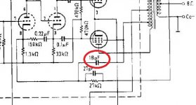
Don't know what Dyna says, but it cap connected to the primary of the transformer functionally bypasses (as in the signal has a shortcut) around the output transformer. The transformer has a leakage inductance and parasitic capacitance that mess up the phase of the feedback signal.
The cap connected to the primary tends to restore that feedback phase.
Caps in the feedback network also provide a transfer function Zero generally located at the frequency of a parasitic Pole in the forward signal path of the amp. Whether to connect the cap to the primary or the secondary of the transformer (or both) is a subtle design trade-off.
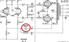
They put the capacitors for those particular output transformers in combination with circuit layout to work right ... it is not something universal that you should do in your amp .
Last edited:
If I categorize it the same way as the one in solid state amp, it should be a cap for miller compensation enclosing the input stage.
No.If I categorize it the same way as the one in solid state amp, it should be a cap for miller compensation enclosing the input stage.
It's a cap for completeing the NFB at higher frequencys. Has nothing to do with miller effect, that is the plate influencing the grid in a negative way reducing
high frequency amplification.
Same thing essentially. Miller Comp. keeps the HF feedback path out of the output stage, Dynaco's fix keeps the HF feedback path out of the OT. In both cases the loop gain thru the global loop is reduced at HF, keeping global N Fdbk stable, and the local loop keeps the gain stage(s) linear still.
Last edited:
True, it has nothing to do with Miller compensation, but everything to do with overall loop compensation so that overall loop has gain and phase margin. It works in conjunction with other compensation means like Miller.
The capacitor of discussion is associated with the particulars of the output transformer as Depanatiru pointed out.
The capacitor of discussion is associated with the particulars of the output transformer as Depanatiru pointed out.
Just goes to show that a Citation II could be built with Edcor OT's if certain tricks are used.
Another simple trick allows removing OT magnetizing current effects and OT primary resistance, leaving a near perfectly transparent OT, to rival OTL sound, without all the heat.
Another simple trick allows removing OT magnetizing current effects and OT primary resistance, leaving a near perfectly transparent OT, to rival OTL sound, without all the heat.
Merlinb posted a link to the patent for fixing an OT's winding resistance using negative resistance for the primary R, back in April. Until I saw that patent (from 1986), I had always mistakenly considered cancelling the full OT resistance. For tube amps, you just put some low value current sampling resistors in the output tube's cathodes, and feed a little Positive Fdbk to the driver stage to increase the drive voltage equal to the OT's resistive drop from that current (Which includes the magnetizing current component). Local Neg. voltage Fdbks will be more accurate as well, besides lowering output Z.
This should give OTL like performance, without all the heat.
The secondary does not have magnetizing current in it, so would require a separate sensing R/Fdbk to fix that winding resistance. One could even go further and cancel some of the speaker coil resistance, but that gets into near oscillation territory. Some global N Fdbk will fix output Z pretty good without the extra secondary neg. R fix.
US4614914A - Low-distortion transformer-coupled circuit
- Google Patents
Last edited:
Merlinb posted a link to the patent for fixing an OT's winding resistance using negative resistance for the primary R, back in April. Until I saw that patent (from 1986), I had always mistakenly considered cancelling the full OT resistance. For tube amps, you just put some low value current sampling resistors in the output tube's cathodes, and feed a little Positive Fdbk to the driver stage to increase the drive voltage equal to the OT's resistive drop from that current (Which includes the magnetizing current component). Local Neg. voltage Fdbks will be more accurate as well, besides lowering output Z.
This should give OTL like performance, without all the heat.
The secondary does not have magnetizing current in it, so would require a separate sensing R/Fdbk to fix that winding resistance. One could even go further and cancel some of the speaker coil resistance, but that gets into near oscillation territory. Some global N Fdbk will fix output Z pretty good without the extra secondary neg. R fix.
US4614914A - Low-distortion transformer-coupled circuit
- Google Patents
Neat trick! Trying that!
- Home
- Amplifiers
- Tubes / Valves
- Dynaco amps, what's the purpose of these caps?