Please, post here pictures of your construction, also any kind of problem you face while assembling and adjusting should be posted here.
Naturally the Dx Supply is also subject of this thread, as it is a part of the kit.
If you are buiding kit or made the pcboard by yourself....then please post it.
regards,
Carlos
Naturally the Dx Supply is also subject of this thread, as it is a part of the kit.
If you are buiding kit or made the pcboard by yourself....then please post it.
regards,
Carlos
Last edited:
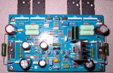
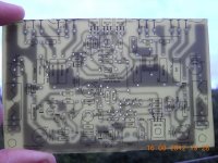
Well..... i have pictures from Juan Vargas
Here you have them
regards,
Carlos
Here you have them
regards,
Carlos
Attachments

And much more to come
I will search images at home..now i am at my work.
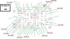
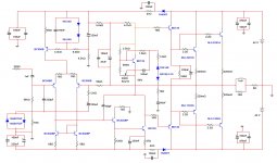
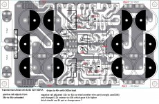
the schematic posted seems not to be the last one..it has not the brazilian colours surrounding (Yellow and Green)
regards,
Carlos
I will search images at home..now i am at my work.
the schematic posted seems not to be the last one..it has not the brazilian colours surrounding (Yellow and Green)
regards,
Carlos
Attachments

Please, post here pictures of your construction, also any kind of problem you face while assembling and adjusting should be posted here.
Naturally the Dx Supply is also subject of this thread, as it is a part of the kit.
If you are buiding kit or made the pcboard by yourself....then please post it.
regards,
Carlos
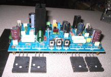
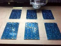
It seems I am very very late to this party....
I didn't see these threads until last week.
back when this was going I was making my first CMOY
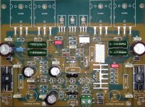
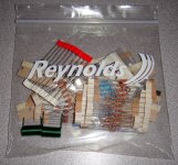
boards are stuffed with what is here and rest will be soon.
heatsinks are from scrap pile, may build or buy real case later.
Thanks to Carlos and all others involved
Attachments

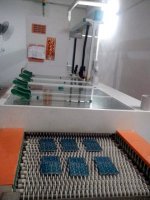
Hello Congo5.
PCB handmade, bravo it's real DIY!
I have a DX - SA and this is a great amplifier, it is very musical and has no worries to stir up speakers greedy.
🙂
PCB handmade, bravo it's real DIY!
I have a DX - SA and this is a great amplifier, it is very musical and has no worries to stir up speakers greedy.
🙂
Thanks Project16 and Hello!
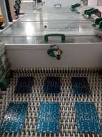
Its DIY if you count the DIY CNC.....that made the boards for me...I think so..🙂
I was on break from building a Monster power amp and here looking for clues
I keep blowing bridge rectifiers, on random startups with 1kva trans and 188,000uf cap bank.
which kills my softstart circuit. or fuse, but not always in time.
anyway found these DX threads and it looked so good... Just had to have one..
short test of DX power supply tonight, that works, led's lit and even voltages. tomorrow I will put a load on it...
then see if I got the amps right....
wish I was here when this was happening.. but plenty of info and things to try
thanks for your comments...
cheers
Last edited:
188000uF is pretty big.
You probably need to look at adopting a slow charge circuit to limit the charging currents into those capacitors.
A soft start is for starting the transformer and that job is done in <<300ms. The timer to bypass the soft start resistor should be done in 100ms to 200ms.
Prolonged high current through a mains soft start resistor will lead to very rapid overheating. A Power Thermistor would survive this if you chose to use a longer delay on the bypass relay. But that still leaves a pretty big current through the rectifier after the transformer has started.
Yes have been looking. Rod Elliot project 39 works if I use a robust thermistor. set for about 1 sec.188000uF is pretty big.
You probably need to look at adopting a slow charge circuit to limit the charging currents into those capacitors.
but need to use better bridges and series thermistors for more resistance
what i have works if the bridges do not blow.
is there any you've tried? can you point to one?
found a mos/opto circuit to detect the capbank voltages and could be used to bypass thermistor
instead of timer.
have been looking for a triac circuit but no joy
thanks
I and many Members disagree on the implementation of soft start and slow charge.
I alledge that a soft start resistor does not operate well as a slow charge current limiter.
It does work very well to allow the transformer to start with a close rated fuse, or even quite a bit smaller.
I alledge that the power thermistor of the slow charge should be in the capacitor charging circuit just like the manufacturers show.
Others say that the soft start can do both duties.
Seems like that might just work.....
going to rebuild my P39 soft start and use 25R resistors,(120v line here) that will handle the primary winding inrush.
and put thermistors between the bridges and caps, that way the transformer does not see a dead short.
and might save my bridges from blowing up. Add a second relay to bypass the thermistors, , timed for 80-90% of full charge voltage.
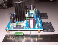
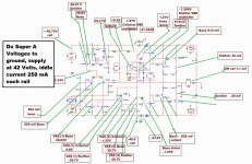
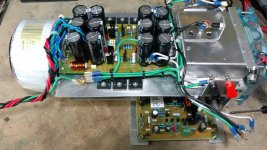
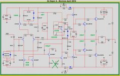
The DX Super A plays music, two things to figure out..............
The power supply negative rail does not adjust properly. right now am running 36.5v rails.
the positive rail does adjust as it should. Below is the board I used and voltages found.
The other thing to track down is amp bias. both channels adjust but voltages are very low.
offset is Good, 10mv on one and 20mv on other, (may change when warm)
I haven't used scope yet but measured less than .5mvac with no signal and 5mv with my finger touching input,(so should be good and quiet)
I've No 10r high watt resistors here so used 5R in power rails to measure, (and variac)
highest it will go is .125mv across the 5.1R so 25ma dc, So about 10% of Spec.
The stuffing guide used is ... April 2015 revision shown below.
tomorrow I may check all the VBE voltages and recheck resistor values, I have been known to add a zero or two on occasion. I built the boards up on different days so unlikely I did the same mistake twice but who knows.
Still it seems stable and does play music on test speakers, and with the bias that low you can turn it off and finish the song .... it plays nicely all the way down to 7v rails.....
Nothing expected, my layout, my boards, I feel good to be this far along.
Thanks
going to rebuild my P39 soft start and use 25R resistors,(120v line here) that will handle the primary winding inrush.
and put thermistors between the bridges and caps, that way the transformer does not see a dead short.
and might save my bridges from blowing up. Add a second relay to bypass the thermistors, , timed for 80-90% of full charge voltage.
The DX Super A plays music, two things to figure out..............
The power supply negative rail does not adjust properly. right now am running 36.5v rails.
the positive rail does adjust as it should. Below is the board I used and voltages found.
The other thing to track down is amp bias. both channels adjust but voltages are very low.
offset is Good, 10mv on one and 20mv on other, (may change when warm)
I haven't used scope yet but measured less than .5mvac with no signal and 5mv with my finger touching input,(so should be good and quiet)
I've No 10r high watt resistors here so used 5R in power rails to measure, (and variac)
highest it will go is .125mv across the 5.1R so 25ma dc, So about 10% of Spec.
The stuffing guide used is ... April 2015 revision shown below.
tomorrow I may check all the VBE voltages and recheck resistor values, I have been known to add a zero or two on occasion. I built the boards up on different days so unlikely I did the same mistake twice but who knows.
Still it seems stable and does play music on test speakers, and with the bias that low you can turn it off and finish the song .... it plays nicely all the way down to 7v rails.....
Nothing expected, my layout, my boards, I feel good to be this far along.
Thanks
Attachments
25r of added resistance should suit starting a 250VA toroid on 110/120Vac.
That will also allow a T2A close rated fuse to survive start up.
25r is far too high for a 1kVA transformer.
That will also allow a T2A close rated fuse to survive start up.
25r is far too high for a 1kVA transformer.
25 to big? yes it is... thanks
Fixed the DX power supply by adjusting the resistor divider that feeds the trim pot.
according to the video ... he said not to mess with those. but don't know another way.. now it adjusts.
using 40v rails
changed a resistor from 820R by piggybacking a 1k (450R) and now the bias adjusts.
set for 26mv across each .47R emitter resitors
Tried it with headphones and speakers, sounds good...
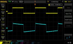
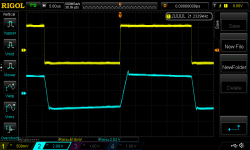
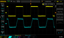
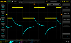
Put on scope.. Not sure what to think...., haven't built many speaker amps.
can a wilma film cap on imput mess up the low freq phase?
Fixed the DX power supply by adjusting the resistor divider that feeds the trim pot.
according to the video ... he said not to mess with those. but don't know another way.. now it adjusts.
using 40v rails
changed a resistor from 820R by piggybacking a 1k (450R) and now the bias adjusts.
set for 26mv across each .47R emitter resitors
Tried it with headphones and speakers, sounds good...
Put on scope.. Not sure what to think...., haven't built many speaker amps.
can a wilma film cap on imput mess up the low freq phase?
Attachments
- Status
- Not open for further replies.
- Home
- Amplifiers
- Solid State
- Dx Super A builder's thread